For each type of hole, an image of a hole is displayed in the dialog.
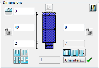
- Change the dimension in one of the following ways:
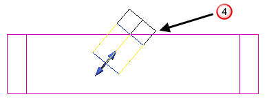
- Drag the edit handles on the hole. It is only possible to use this method if you have already positioned the hole on the solid.
- Enter values in the dimension boxes.
- Use the following buttons to specify the way the hole is extended or limited:
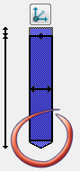
 — Select this option to extend the hole all the way through the solid. On the screen, the length of the hole extends beyond the solid. Safety margins are drawn at both ends of the hole.

 — Select this option to limit the length of a hole, that is longer than the thickness of the solid, to that thickness. Deselect this option so that the length of a hole is not limited.
 — Select this option to limit the length of the through hole to the final forward intersection. If you want to limit the length of the through hole to the first intersection, click
to display
— Select this option to limit the length of the through hole to the final forward intersection. If you want to limit the length of the through hole to the first intersection, click
to display
 .
.
 — Select this option to limit the backward length of the hole to the final intersection. If you want to limit the length of the backward hole to the first intersection, click
to display
— Select this option to limit the backward length of the hole to the final intersection. If you want to limit the length of the backward hole to the first intersection, click
to display
 .
.
- Use the following buttons to specify how the depth is measured and the end of the hole:
 — Select this option to measure the depth of the hole to its shoulder. Deselect this option to measure the depth of the hole to the tip of the cone. If this button is selected, the
Display the end of the hole
— Select this option to measure the depth of the hole to its shoulder. Deselect this option to measure the depth of the hole to the tip of the cone. If this button is selected, the
Display the end of the hole
 button becomes inactive.
— Select this option to display a cone at the end of the hole.
button becomes inactive.
— Select this option to display a cone at the end of the hole.
If
 is displayed, chamfers are added to the hole sections as defined in the
Chamfer Hole
dialog. Click
is displayed, chamfers are added to the hole sections as defined in the
Chamfer Hole
dialog. Click
 to display the
Chamfer Hole dialog.
to display the
Chamfer Hole dialog.
If no chamfers are required, click
. This removes
 and no chamfer
 is displayed.
- Use the following option to specify the safety margin:
 — Select this option to set safety margins to an automatically generated value, that is large enough to ensure that the hole completely passes through any surface intersections. The offset safety distance text box is inactive. Deselect this option to set the offset safety distance manually.
The safety margin is the length above the hole which ensures that the hole cuts into the solid
 . If you can see that the safety margin lies inside the solid, increase it.

In the figure below, the safety margin lies inside the solid
 .
.

The safety margin value is increased so it lies outside the solid
 .
.
- Use the following buttons to lock and unlock the depth and the diameter.
 the dimension is locked. Click to unlock.
 the dimension is unlocked. Click to lock.
- If the depth is locked, the depth of the hole does not change when the whole solid is uniformly scaled from the Edit tab. If the depth is unlocked, the depth is scaled too.

 Unscaled solid shows the original depth.
Scaled solid with locked depth shows the original depth.
Scaled solid with unlocked depth shows the scaled depth.
Unscaled solid shows the original depth.
Scaled solid with locked depth shows the original depth.
Scaled solid with unlocked depth shows the scaled depth.
If you non-uniformly scale the solid or define the depth of the hole using parameters, the depth is not scaled regardless of whether it is locked or unlocked.
- If the diameter is locked, the hole diameter does not change when the whole solid is uniformly scaled from the Edit tab. If the diameter is unlocked, the diameter is scaled too.
 Unscaled solid shows the original diameter
 Scaled solid with locked diameter has original diameter
 Scaled solid with unlocked diameter has scaled diameter
If you non-uniformly scale the solid or define the diameter of the hole using parameters, the diameter is not scaled regardless of whether it is locked or unlocked.
- If the depth is locked, the depth of the hole does not change when the whole solid is uniformly scaled from the Edit tab. If the depth is unlocked, the depth is scaled too.