You can add the following types of holes to a solid by specifying the use of the hole.

To create holes in or through a solid:
- Create a solid or open a model with a solid:
- Click Solid tab > Feature panel > Hole to display the
Plain Hole dialog:

- Select the
Hole Category from the drop-down list:
- General Machining (ISO)
- Precision Machining (ISO)
- Molding
- Untoleranced
- Select the specific
Use
of the hole for the category you have chosen.
With the exception of untoleranced holes, machining tolerances based on the intended use are also stored when the hole is created.
Tip: You can add your own hole categories and uses on the Holes page of the Options dialog.The options displayed on the dialog reflect the Hole Category and Use you have chosen.
- Use
 to swap between creation mode and editing mode without closing/reopening the dialog.
- When in creation mode, click
to swap to editing mode and recognition mode.
- When in editing mode, click
 to swap to creation mode.
- When in creation mode, click
- If available, click
 to display information on usage of the selected hole and an example of the application.
If available, click
 to display the
Plane Details dialog. This option is only available when you have positioned the hole.
to display the
Plane Details dialog. This option is only available when you have positioned the hole.
- When
 is displayed, the hole is considered for machining in
PowerMill. Clicking
changes the button to
is displayed, the hole is considered for machining in
PowerMill. Clicking
changes the button to
 .
.
When
is displayed, the hole is ignored when exporting to
PowerMill.
- Use the following sections to set type-specific options for:
- Counterbored holes — Use the standard Dimensions options to set the dimensions to match standards that fit screw sizes easily.
- Tapped holes:
- Select an option from the Standard drop-down list.
- Specify the
Size by selecting a value from the drop-down list. The size of the pre-defined tapped holes corresponds to a drill size in the appropriate units.
Alternatively, select User Defined and enter your own values in the dimension boxes, or use a parameter to specify the diameter of a tapped hole. The hole is set to the tapping size closest to the value of the parameter.
- Countersunk
- Use the Dimensions options to specify the size and trim attributes of the hole.
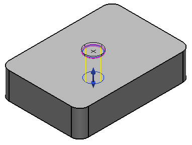
- Click the solid to position the hole centre. The hole is drawn on the solid.
- To finish creating the hole, click one of the following:
-
Apply — Create the hole, keep the dialog open, and remain in hole creation mode. You can click the solid again to add another hole. The new hole is the same as the last one created; the Hole Feature dialog is displayed for you to modify the hole.
Note: The next hole is created using the default settings unless you select the Reuse Last Hole Definition option on the Holes page of the Options dialog.
- OK — Create the hole as defined and close the dialog.
Note: If changing a value on the Hole dialog invalidates the hole definition, the status bar help for the unavailable Accept and Apply buttons indicates the values are incorrect.A Hole feature
 icon representing the operation appears in the solid feature Tree Window. After 20 holes are created in the solid, you are asked whether you want to
optimise the tree.
icon representing the operation appears in the solid feature Tree Window. After 20 holes are created in the solid, you are asked whether you want to
optimise the tree.
-
Apply — Create the hole, keep the dialog open, and remain in hole creation mode. You can click the solid again to add another hole. The new hole is the same as the last one created; the Hole Feature dialog is displayed for you to modify the hole.