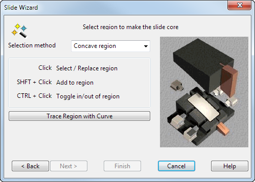
Use this page to select the undercut region.
An arrow is drawn, pointing in the direction of the +Z axis. This shows the direction of puller.
If the wrong workplane is selected, you can select another one using the
Workplane drop-down list
 in the bottom left corner.
- Select an undercut region on the solid where you want to create a core puller.
As you move the cursor over the solid, regions highlight. These are the regions you can select.
If you click a highlighted region, it is selected and changes colour. Note that any regions already selected are removed from the selection.
You can add and remove regions from the current selection using the Shift and Ctrl keys as shown on the wizard.
You can use box selection to select regions. Only whole faces within the box are selected, which makes it easier to select groups of faces. You can also use box selection with the Shift and Ctrl keys to add and remove regions.
Selection method — These three options determine what type of region is highlighted:
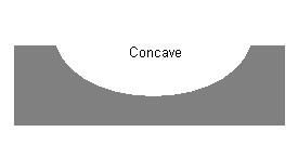
Concave region — Highlights concave regions on the die insert.
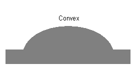
Convex region — Highlight convex regions on the die insert.
Single face — Highlights only single faces.
Trace Region with Curve — You can trace a closed curve on the active solid to define the region. Click Trace Region with Curve to display the Create Composite Curve toolbar. Use the toolbar to select a curve. The curve is coloured the same as regions selected using the automatic method. For further details, see Creating a composite curve by tracing.
The Trace Region method is intended to be used when the automatic selection fails because the solid is linked badly or the region is too complex. The Trace Region method takes longer to compute the undercut region so try the selection method first whenever possible on the Extension Distance Options page.
- Click Next to display the Extension Distance Options page of the wizard.