This sets the options for the slide core.
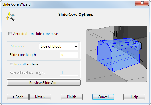
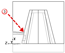
- If you want a zero-draft angle on the slide core base, select the
Zero draft on slide core base
option. The base of the solid core is trimmed to the split surface.
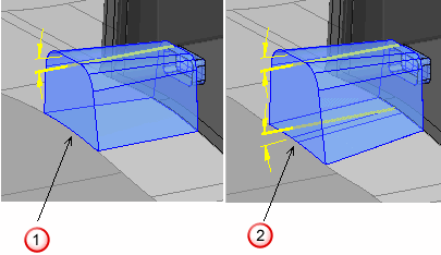
 — No draft angle at the base
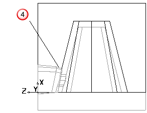
 — Draft angle at the base
- Select the
Reference
point for measuring the slide core length from the following options.
Side of block - Side of Cavity/Core insert.
Contact profile - Maximum Z of the contact profile.
Slide core front - Minimum Z of the undercut surfaces.
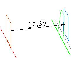
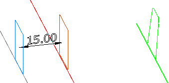
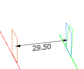
- Set the
Slide core length from the reference point.
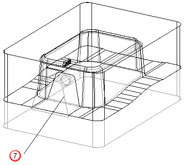
The reference is shown as a blue plane and the other plane shows the extent of the slide core. The dimension on the model shows the distance between the two planes.
If the slide core does not extend to the edge of the insert, the Split Surface Modification page is not available.
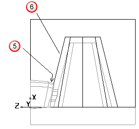
- If you want a run off surface on the slide core base, select the
Run Off Surface option.
If you have a sharp edge
 at the top of the base where it touches the die plate, you can add a run off surface to prevent it from wearing.
The run off surface
 is added at the sharp edge.
Input a value for the length
 . This length is measured along the normal of the die plate
 .
.
- Click
Preview Slide Core to see the preview of the core.

- Click
Next or
Finish:
- Click Next to display the Split Surface Modification page of the Slide core wizard, where you can modify the split surfaces.
- Click Finish to remove the shape of the core from the die insert, on which the undercut was selected. The split surfaces will not be modified to allow the core to fit.
If you selected the Zero draft on slide core base option, you can only click Finish as there is no need to modify the split surface.