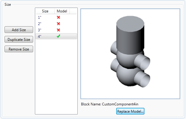
In the Catalog Editor, create a component using custom geometry. Specify the piping component class and other fixed properties of the new component. Generate an initial size range. Add and remove sizes to match the custom component blocks. Import Custom geometry for each size.
To create a component using block based geometry
- In the Catalog Editor tab, click Create New Component.
- Click Custom - AutoCAD DWG Block Based Graphics.
- In Basic Part Family Information, click a component category (for example: Valves).
- Click a Component type (for example: Valve).
- Enter a Short Description (for example: DOUBLE SEAT VALVE).
- Click a Primary End Type (for example: BV). You can also enter a value if the Primary End Type is not in the catalog.

- Enter the Number of Ports (for example: 4). This value must match the number of ports added to the custom component blocks.
Sample Blocks
![]() AP3D_Custom_Component_Sample (zip).
AP3D_Custom_Component_Sample (zip).
To assign sizes to a block based component
- In Size Range, specify a size range. For example 1” to 4”.
- Click Create.
- In the Piping Component Editor pane, click the Sizes tab.
- If there are sizes that you do not want in the size column, click a size. Click Remove Size.
- In Size, click a size to set a block and properties (for example: 4”).
- Click Select Model.
- In the Select Block Definition dialog box, open a drawing and click a block that has ports specified using
plantpartconvert.

- In Connection Port Properties, enter Matching Pipe OD (for example: 4.5).
- Do
one of
the following:
- If all connection port properties are the same, select All Ports Have the Same Properties.
- Click the right arrow and enter the Matching Pipe OD for additional ports.
- In Piping Component Properties, enter a Long Description (Size). (For example, DOUBLE SEAT VALVE, 4”).
(continued from To create a component using block based geometry)