You can specify the maximum length of pipe segments when routing in the 3D model.
Fixed-length pipe is useful when you create a 3D model using grooved, plain-end mechanical, and flanged-end piping connections. You can download content packs that include AWWA, BPE, Victaulic, and Resistoflex piping catalogs.
You can also set up welded piping as fixed-length piping. Fixed-length piping is enabled by selecting the Use Fixed Length property in the piping spec.
If fixed-length piping is not specified (the default), joints are not placed in the 3D model for a single length of straight piping. You can specify a field weld location (for example: using plantweldadd). However, the maximum length of tubing is normally not considered until you generate an Isometric drawing (along with the Iso Bill of Material).
Pipe Routing
When using pipe from a piping spec with fixed-length enabled, you route pipe just as you would with any other spec (fixed-length disabled).
You can specify the same routing options (plantpipeadd), use the continuation grip, and so on. You can also place components from the tool palette and connect them into the line. The most noticeable difference is that when you route fixed length piping, as you exceed the Fixed Length property, the 3D modeler begins a new pipe segment and connects to the maximum length segment.
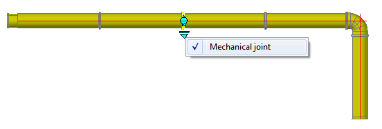
A mechanical or flanged connection commonly exists at the ends of each pipe segment. These connections are similar to other connections. However, you may need to modify the joint configuration settings in Project Setup to support the connections. You can also update the project DefaultConnectorsConfig.xml following the installation instructions (readme) from a content pack.
If a fixed-length pipe segment is at maximum length the pipe is not cut back.
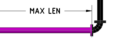
For example, if you change direction when routing such that an elbow is added to the end of a maximum length pipe, the overall dimension lengthens. This differs from other piping where routing a turn will shorten (cut-back) the pipe segment to retain the centerline endpoint.
Orthographic drawings (Orthos)
You create Ortho drawings for fixed-length piping the same as you do for other piping, except that you have an additional option for the Ortho BOM.
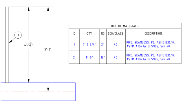
When creating an Ortho BOM for fixed-length piping, you can set up the BOM to report custom length (shorter than the maximum length) on separate lines in Table Setup.
Isometric drawings (Isos)
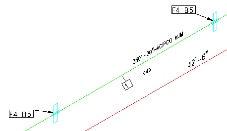
Isometric drawings (Isos) for fixed-length piping is similar to other piping. However, fixed-length piping frequently has end types that should be illustrated in the Iso drawing. This differs from plain, welded, or threaded (BV, PL, THD) which do not display symbols to indicate the end type.

Ortho and Iso BOM
Bill of Materials reports allow you to list each length of fixed-length piping on a separate line item.

For more information see Settings Tab (Table Setup Dialog Box).
Piping with an Existing status is no longer included in an Ortho BOM.
Stub-in connections now display the cut-back length in both the Ortho drawing and the 3D Model.