Create a new Isometric Style. For example, you can create a style for spool drawings.
- Click Home tab
 Project panelProject ManagerProject Setup.
- In the Project Setup tree view, expand Isometric DWG Settings. Click Iso Style Setup.
- Do one of the following:
- To create a new style, click Create New Iso Style. In the New Iso Style dialog box, enter a name and select a style on which to base the new style. The new name displays in the Iso Style box.
- To modify an existing style, select the style you want to modify from the Iso Style drop-down list.
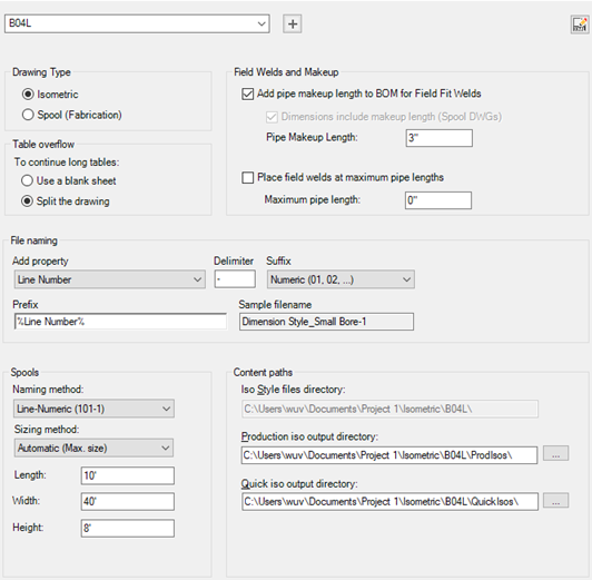
- Under Iso Style Information, do the following:
- Under Drawing Type, click the type of drawing to which the style is applied, Isometric or Spool.
Note: If you select Spool Drawing, File Naming and Under Table Overflow are not available.
- Next to File Naming (Isometric drawings only), select a naming scheme, either alphabetical or numeric (default).
- Select the check boxes as appropriate and enter maximum and makeup pipe length values.
- Under Table Overflow (Isometric drawings only) specify whether to flow table data onto a new drawing sheet or split the iso into two smaller isos.
- Under Drawing Type, click the type of drawing to which the style is applied, Isometric or Spool.
- Under Spools, do the following:
- Select whether to determine the spool automatically by maximum size or maximum weight and enter the values as appropriate. Or you can choose to use the spool number from the model.
Note: Your selection here determines the fields that become available.
- Select the check box if you want the program to identify maximum pipe length segments as spools.
-
Select the check box if you want dimensions to include makeup length in spool drawings.
- Select whether to determine the spool automatically by maximum size or maximum weight and enter the values as appropriate. Or you can choose to use the spool number from the model.
- Under Iso Style Paths, do any of the following:
- Enter location paths for the style files directory, the production iso output directory, and the quick iso output directory.
- Click the [...] button to the right of each box to browse to the desired location.
- Click OK.
Create a new iso style
- Click Home tabProject panelProject ManagerProject Setup.
- In the Project Setup dialog box, expand Isometric DWG Settings. Click Iso Style Setup.
- On the Iso Style Setup pane, click Create New Iso Style.
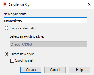
- In the Create Iso Style dialog box, under Name, enter a name for the new iso style.
- In the Base on Existing Style list, click an existing iso style on which to base the new style.
- Click Create.