Specify the location of the tables and the reports (BOM and lists) that you want to include. You can also customize the columns and grouping in the report.
- On the ribbon, click Home tab
 Project panel Project Manager Project Setup.
 - In the Project Setup tree view, expand Isometric DWG Settings. Click Title Block and Display.
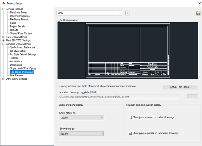
- On the Title Block Display pane, next to Iso Style, select a style from the drop-down list.
- Under Title Block Preview, click Set Up Title Block.
- In the ribbon, Table Placement & Setup panel, click Table Setup
 .
.
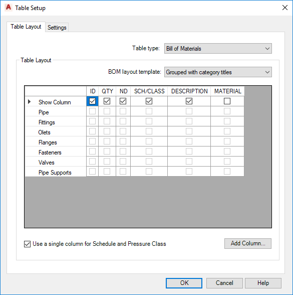
- In the Table Setup dialog box, Table Layout tab, do the following:
- Next to Table Type, select a type from the drop-down list.
- (Applies to BOM only) Next to BOM Layout Template, select a template from the drop-down list. Choices include Simple BOM, Grouped with Category Titles, or Grouped with Independent Columns.
- Select or clear the check boxes to specify which fields to include in the BOM or list.
- Right-click to rearrange rows in table. You can also drag and drop columns.
- To add a column, click Add Column. In the Select Class Property dialog box, select a property for inclusion as a column header. Click OK.
- Make further changes to the title block as needed, using the contextual ribbon commands.
- When finished, on the ribbon, Close panel, click Return to Project Setup.
To configure BOM settings
- On the ribbon, click Home tab Project panel Project Manager Project Setup.
- In the Project Setup tree view, expand Isometric DWG Settings. Click Title Block and Display.
- On the Title Block Display pane, next to Iso Style, select a style from the drop-down list.
- Under Title Block Preview, click Set Up Title Block.
- In the ribbon, Table Placement & Setup panel, click Table Setup
.
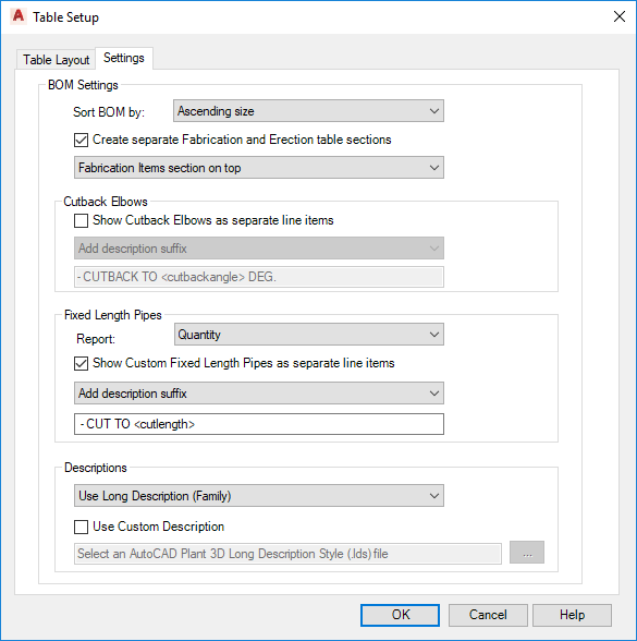
- In the Table Setup dialog box, Settings tab, do the following:
- Under Sort BOM By, select a sort order.
- Select or clear the Create Separate Fabrication and Erection Table Sections. If you select the check box, you can also select the section order from the drop-down list.
- Select or clear the Show Cutback Elbows as Separate Line Items. If you select the check box, you can then add a prefix or suffix to further distinguish the elbow for a standard elbow. You can also see a preview of the resulting display.
- Select or clear the Use Custom Description check box. If you select the checkbox, click the [...] button to locate the AutoCAD Plant 3D toolset Long Description Style (.lds) file you want. This file will set the format for all descriptions in the BOM. Click OK.
- Make further changes to the title block as needed, using the contextual ribbon commands.
- When finished, on the ribbon, Close panel, click Return to Project Setup.