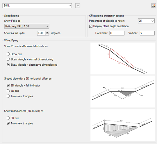
Specify how you want slopes and skews to be identified in the isometric drawing.
- On the ribbon, click Home tab
 Project panel Project Manager Project Setup.
 - In the Project Setup dialog box, expand Isometric DWG Settings. Click Slopes and Skews.
- On the Sloped Lines pane, in the Iso Style list, select an iso style.
- Under Sloped Piping, do the following:
- Under Show Falls as, select a falls behavior option from the drop-down list. Options include Angle, Ratio, Percentage, Gradient, Imperial Incline, Metric Incline, or Suppress Falling Line Indication.
- Under Show as fall up to, select a value from the drop-down list or enter a value to specify the maximum value at which falls display.
- Under Offset Piping, do the following:
- Under Show 2D Vertical/Horizontal Offsets As, click Skew Box, Skew Triangle + Normal Dimensioning, or Skew Triangle + Alternative Dimensioning.
- Under Show Pipe With a 2D Horizontal Offset As, click 2D Triangle + Fall Indicator. 3D Box, or Two Skew Triangles.
- Under Show 3D Skews as, click 3D Box or Two Skew Triangles.
- Click OK.