Use this dialog to define the code parameters of a member type according to the SP16.13330.2017 code.
Access
- Click
Design
 Steel Members Design - Options
Code parameters to open the Member Type dialog, and then click
Steel Members Design - Options
Code parameters to open the Member Type dialog, and then click
 .
.
- Click Parameters in the Definitions dialog.
Dialog elements
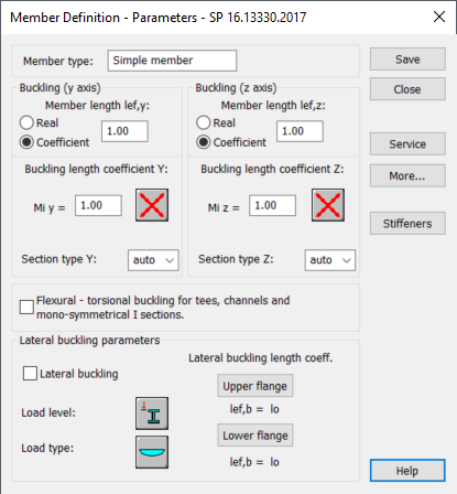
- Member Type
- Specifies the name of the selected member type.
Note: You can enter a new name in the member type box.
- Buckling (y axis) and Buckling (z axis)
- Use the Buckling (y axis) and Buckling (z axis) options to determine the length of a member for the appropriate plane.
-
Enter a value in the member length box, and then define this length in either of the following ways:
- Select Real, to use the value in the member length box as the member length.
- Select Coefficient, to use the value in the member length box as the coefficient by which the real member length should be multiplied to obtain the required value. For example, if the value 0.25 is entered, it means that the relevant member length equals 1/4 of the real length.
Note: For a simultaneous definition of several members whose actual lengths differ and e.g. additional supports are equally spaced, the second method mentioned is very convenient. If the parameters set are to be saved as a category, such a manner of entering the length is necessary. If the value 1.0 is entered, it guarantees that each member defined using the category as Ly will have its actual length accepted. - Buckling length coefficients (Y and Z)
- Use the buckling length coefficients options to define the member buckling length coefficients.
The actual bar length (or the sum of the component member lengths) is automatically entered in the appropriate fields.
The Buckling length coefficient depends on the end-support condition of member nodes in the buckling plane.
Click
 or the icon corresponding to the selected buckling type, to open the Buckling types dialog which allows you to define the buckling length of a member. Typical member support schemes are provided here; when one of them is selected, the coefficient value will be accepted or calculated automatically.
The icons in the Buckling types dialog are divided in two groups:
or the icon corresponding to the selected buckling type, to open the Buckling types dialog which allows you to define the buckling length of a member. Typical member support schemes are provided here; when one of them is selected, the coefficient value will be accepted or calculated automatically.
The icons in the Buckling types dialog are divided in two groups:- Typical (code) methods of member support and the corresponding values of buckling coefficients.
- Options used to calculate buckling coefficient for columns of multi-story frames.
Buckling is always considered during calculations when a compressive force acts on a member, even if it is negligible in comparison to other internal forces. The program does not perform - on its own - a separate analysis that would determine if buckling effects may be disregarded or not.
Select
to exclude buckling effects from the calculations.
The section types for each buckling direction allows for taking appropriate coefficients ( α , β ) according to the Table 7 for obtaining the buckling coefficient ϕ - see 7.1.3 formula (8).
- Flexural-torsional buckling check for tees, channels and mono-symmetrical I sections
- Select this option to perform an additional check of members made of specific types of shapes against flexural-torsional buckling according to the provisions given in 7.1.5 and Annex D.
- Lateral Buckling Parameters
- Use the Lateral Buckling Parameters to select which options to use during the verification of member lateral buckling.
- Lateral buckling
- Select this option to take into account the code requirements concerned with lateral buckling during the member calculations.
- Load level
- Click the Load level icon, and then select a type of load level.
Note: A load level is a load acting on lower or upper flange.
- Load Type
- Click the Load Type icon, and then select a type of load.
- Click the Load level icon to select the type of load level.
- Lateral buckling length coeff.
- Lateral buckling calculations require that the distance between sections protected against torsion, also called lateral buckling length, be specified for a member. Due to the possibility of supporting the upper or lower flange separately and the occurrence of compressive stresses in upper or lower flange for different load cases, two lateral buckling lengths are distinguished. There is a coefficient provided, by which the base member length should be multiplied to obtain lateral buckling length. As base length, the lz length is assumed.
- Enter a coefficient value directly or choose an icon with typical support case for which the coefficient will be selected automatically.
Note: The symbols included in the Lateral buckling length Coeff. dialog are explained in the Detailed Results tab of the Results dialog. This dialog contains definitions of all the parameters assumed for steel member calculations and result values obtained after member calculations.
- More
- Opens the Member definition - additional parameters dialog which allows you to define the remaining member type parameters described in the code such as: equivalent moment factor, section parameters, etc.
- Service
- Opens the Serviceability - Displacement Values dialog which allows you to define the limit displacements for a member.
- Stiffeners
- Opens the Location of transverse stiffeners dialog which allows you to define transverse stiffeners along the member length.
- Save
- Adds the member type with its defined name and determined parameters to the list of previously defined steel member types.