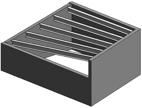
Create non-planar beam systems in which the elevation of a beam is defined by its sketch lines.
- Click Structure tab
 Structure panel
 (Beam System).
- On the Properties Palette, select 3D so that the framing elements of the beam system will snap accordingly to its supports.
- If you have a closed loop of supporting elements for the beam system, click Modify | Create Beam System Boundary tab Beam System panel
 (Automatic Beam System). Select Walls, Define Slope on the Options Bar, and click to place the beam system.
Otherwise, click Modify | Place Structural Beam System tab
Beam System panel
(Sketch Beam System). Sketch the beam system using the Draw panel tools, including Pick Lines and Pick Supports.
Note that sketched beam lines- Can only define slope when they are created using the Pick Supports tool.
- That have a beam as their support always define slope.
- That have a wall as their support have a Defines slope property that you can edit. The default value is true.
- If you sketched the beam system boundary, click Modify | Create Beam System Boundary tabMode panel
 Finish Edit Mode.
- If the end of the beam connects to a sketch line that defines slope, the beam is connected to the top of the associated support.
- If the sketch line does not define slope, then the end of the beam is elevated to a plane defined by the endpoints of the 2 nearest sketch lines that do define slope.
- If there are no lines in the sketch that define slope, the beam system behaves like a 2D beam system.