Use the In-Place Wall tool to create a wall that you design manually using unique geometry that is not possible with the other Wall tools.
- Click one of the following:
- Architecture tab
 Build panel
 Wall drop-down
 (In-Place Wall)
 - Structure tab
 Structure panel
 Wall drop-down
 (In-Place Wall)
- Architecture tab
- Enter a name for the new in-place wall type.
The Family Editor opens, and existing geometry in the building model displays in halftone.
- Use the Family Editor to design the wall.
For example, on the Create tab
 Forms panel, use the Extrusion, Blend, Revolve, Sweep, Swept Blend, and Void tools to create the geometry of the in-place wall. See Creating Solid and Void Geometry and Sketching Elements.
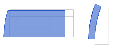
 The following image shows an in-place wall in an elevation view and a plan view. Other geometry in the model displays in halftone.

- Click
 (Finish Model).
 The in-place wall displays in the model.
- In the project environment, continue designing the model.
