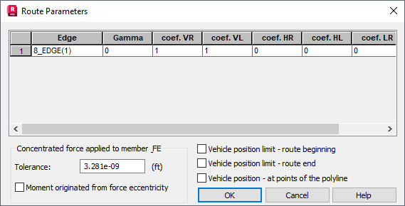
The option determines scaling coefficients that let you obtain the real (calculation) value of a load originating in a moving vehicle. The option is available by clicking Parameters in the Moving loads dialog.

The dialog has a table displaying the parameters of a route (polyline):
- Edge column - The number and name of the polyline defining the vehicle route.
- Gamma column - A vehicle can revolve around the vertical axis. It changes the position of forces (their direction remains unchanged). Rotation is determined by the Gamma angle, defined in the same way as the Gamma angle for describing the characteristics of bar elements.
- coefficient VL column - The scaling coefficient for the vertical force (V) operating from the left. It allows Robot to multiply the load value (such as, a concentrated force) to obtain the real (calculation) value of the load.
- coefficient VR column - The scaling coefficient for the vertical force (V) operating from the right. It allows Robot to multiply the load value (such as, a concentrated force) to obtain the real (calculation) value of the load.
- coefficient HL column - The scaling coefficient for the transversal horizontal force (H) operating from the left. It allows Robot to multiply the load value (such as, a concentrated force) to obtain the real (calculation) value of the load (the horizontal load perpendicular to the route direction).
- coefficient HR column - The scaling coefficient for the transversal horizontal force (H) operating from the right. It allows Robot to multiply the load value (such as, a concentrated force) to obtain the real (calculation) value of the load (the horizontal load perpendicular to the route direction).
- coefficient LL column - The scaling coefficient for the longitudinal horizontal force (L) operating from the left. It allows Robot to multiply the load value (such as, a concentrated force) to obtain the real (calculation) value of the load (the horizontal load parallel to the route direction).
- coefficient LR column - The scaling coefficient for the longitudinal horizontal force (L) operating from the right. It allows Robot to multiply the load value (such as, a concentrated force) to obtain the real (calculation) value of the load (the horizontal load parallel to the route direction).
If coefficients on the right and on the left have different values, intermediate coefficients within the width of a vehicle are interpolated depending on its width. In addition, you can apply the options used to limit a vehicle position on a structure.
The bottom of the dialog box has the Tolerance field. It is a parameter assigned to a defined moving load analysis case. Tolerance determines the conditions for generating loads that originate from a defined vehicle, on bars. If the Moment originated from force eccentricity option is selected, a concentrated moment load from a concentrated force is generated and applied to the bar considering the eccentricity.
At the bottom of the dialog, there is also the Vehicle position - at points of the polyline option, whose main task is to position a vehicle load on the route of a moving load at points of the polyline (characteristic points located along the route of the vehicle). If the option is selected, the load resulting from the vehicle is applied at the end of every polyline segment. By standard, a vehicle position is determined by means of a step of the vehicle movement; therefore, when using this option you can ensure that the vehicle load is positioned at certain specified points (such as, a support).
Example
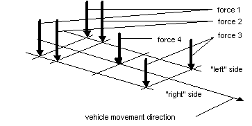
A set of forces is defined for a vehicle as shown in the following image.

Defining the following coefficients:
VL = 1.0
VR = 1.0
HL = 0.0
HR = 0.2
LL = 0.1
LR = 0.0
Results in the following values of forces:
Force 1: VL = 1.0, VR = 1.0, HL = 0.0, HR = 0.2, LL = 0.1, LR= 0.0
Force 2: VL = 1.0, VR = 1.0, HL = 0.0, HR = 0.2, LL = 0.1, LR= 0.0
Force 3: VL = 1.0, VR = 1.0, HL = 0.0, HR = 0.2, LL = 0.1, LR= 0.0
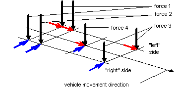
Force 4: VL = 1.0, VR = 1.0, HL = 0.0, HR = 0.1 (average of the values HL and HR), LL = 0.1 (average of the values LL and LR), LR= 0.0
For this polyline, the load takes the shape as shown in the following image.

See also:
Program operation during the definition of coefficients (load multiplication coefficients)