3D Mesh modeling provides several methods to create free-form designs by stretching, twisting, scaling, and smoothing meshes.
You can choose from the following tools to facilitate this process.
Smooth a Mesh
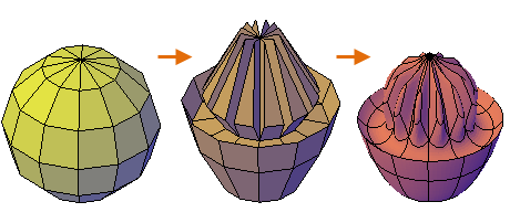
Mesh smoothness is an object-specific property of 3D meshes. An unsmoothed mesh has a smoothness level of 0, and mesh smoothness can go up to 256, although meshes commonly use only levels 1 through 4. In the following illustration, a mesh sphere is modified by grip editing and extrusion, and then smoothed.

You can work more efficiently when you complete editing operations using gizmos, extrusion, and splitting faces on mesh objects that have not been smoothed yet. You can quickly switch between the levels of smoothness using the Properties palette to get previews of the selected mesh. Higher levels of smoothness increase complexity, which affects performance.
Select Subobjects with Selection Filters
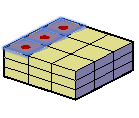
Selecting a subobject in a mesh can be difficult unless you specify one of the subobject filters, which are accessible from the Mesh tab, Selection panel. By specifying that selection is limited to faces, edges, or vertices, you can restrict which subobject type can be selected. In the following illustration, the Face subobject selection filter is turned on, and you can select faces individually or with the Window or Crossing options.

Extend or Extrude Mesh Faces
You can extend one or more mesh faces with a 3D gizmo, which displays when you select each face, or you can extrude one or more mesh faces with the MESHEXTRUDE command. A key difference between extending and extruding mesh faces is apparent from the way each face is modified using identical distances.
With 3D gizmos, when you modify selected faces, the adjacent faces are stretched to accommodate the modification. When the object is smoothed, the adjacent faces adapt to the new location of the faces. In the following illustration, the highlighted mesh faces are extended using the 3D Move gizmo, and then smoothed.

Mesh extrusion, however, inserts additional faces to close the gap between the extruded faces and the original mesh surface. With mesh extrusion, you can specify whether adjacent faces are extruded either as a unit (joined) or separately (not joined) as shown in the following illustration.

Maintain Edges with Creases
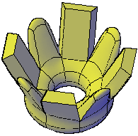
To help limit the distortion when a mesh is smoothed you can crease selected edges, which will maintain their sharpness no matter how much the mesh is smoothed. You might also need to crease the edges in surrounding faces. The following illustration displays extruded faces on a mesh torus, alternately creased and uncreased.

When you set the Creased parameter to Always, the creased edge retains its sharpness after smoothing. Otherwise, the creased edge becomes smoother at the equivalent level of smoothness.
Subdivide the Faces on a Mesh
When you refine a mesh, one or more faces are subdivided into smaller faces for finer control. However, by increasing the number of faces, you add to the overall complexity of the model. In addition, refining an entire mesh object resets the base level of smoothness to 0. This change can result in a dense grid that can no longer be simplified. For best results, avoid refining the object, and refine or split only the individual faces that require more detailed modeling. The following illustration demonstrates the result when a smoothed mesh box is refined entirely, or when only one face is refined.

Convert Meshes to 3D Solids or Surfaces
If you need to edit mesh objects through intersection, subtraction, or union, you can convert a mesh to a 3D solid or surface. Similarly, if you need to apply creasing or smoothing to a 3D solid or surface, you can convert it to a mesh. However, not all conversions retain complete fidelity to the shape of the original object. Avoid switching between object types more than once, if possible. If you notice that the conversion modifies the shape of the object in an unacceptable way, undo the conversion and try using different settings.
Avoid Problems with Meshes
You might have trouble converting some meshes to 3D solids due to the following problems:
-
Gaps in the mesh. If you notice gaps, you can sometimes close them by smoothing the mesh, by refining the faces that are adjacent to the gap, or using MESHCAP. In the following illustration, a mesh was twisted using 3D Rotate at several smoothing levels.

-
Intersecting mesh faces. Avoid creating self-intersecting meshes when you move, rotate, or scale subobjects. This can occur when you cause one or more faces to cross or intersect other faces in the same mesh object. In the following illustration, the top faces of the mesh were dragged past the bottom faces.

View the mesh from several viewpoints to ensure you create a viable model.
- Faces that Wrap Corners. When you merge faces, you can create a mesh configuration in which the merged face wraps a corner. If a resulting face has a vertex that has two edges and two faces, you cannot convert the mesh to a 3D solid object.

Mesh objects that cannot be converted to solids can often be converted to surfaces instead. One way to resolve this problem is to convert the mesh to a faceted solid instead of a smooth solid. You might also be able to repair the problem by splitting the adjacent faces, starting at the shared vertex (MESHSPLIT).