Inserts a parametrically generated PLC I/O module.
Find Command entry:
AEPLCP
Command entry:
AEPLCP
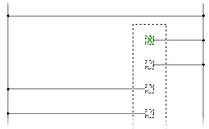
Generate PLC I/O modules on demand in a variety of graphical styles with no complete I/O module library symbols. Modules adapt to the underlying ladder rung spacing. You can stretch or break them into two or more pieces at insertion time. A PLC database, ACE_PLC.MDB, drives generation. It contains the stack sequence and the text values to annotate onto each symbol in the stack.
Manufacturer Catalog tree
Provides a complete list of the PLC modules available to AutoCAD Electrical toolset. The Manufacturer Catalog tree is compiled from the database file, "ace_plc.mdb."
Module List
Displays the defined modules. Once you select a module type or a specific module from the Manufacturer Catalog tree, AutoCAD Electrical toolset reads through the information contained in the database. Select from this list to begin the PLC module insertion process.
Graphics Style
Specifies the graphical appearance of the PLC module. Styles 1-5 are provided with AutoCAD Electrical toolset. Styles 6-9 may be user-defined. Select a style number and a sample portion of a PLC module displays.
To create a user-defined style: There are about two dozen symbols associated with each style. They are located in \Users\Public\Documents\Autodesk\Acade {version}\Libs\{library}\.
The symbols carry the file name "HP?*.dwg" or "VP?*.dwg" where "?" is the style number. An easy way to create a style is to copy the symbols of an existing style to one of the unused style numbers (6, 7, 8, or 9) and edit each library symbol.
Scale
Specifies the scale for the PLC module. You can also specify to apply the scale only to the border of the PLC module.