You can generate a PLC module dynamically, insert a full PLC unit, or insert PLC I/O points as individual symbols.
Generating PLC Modules
AutoCAD Electrical toolset can generate any number of different PLC I/O modules on demand and in various graphical styles. AutoCAD Electrical toolset generates the selected PLC I/O module through a parametric generation technique based on information in the PLC database (ACE_PLC.MDB).
The PLC database contains the stack sequence and text values to annotate onto each symbol in the stack. As AutoCAD Electrical toolset builds the module, it reads the underlying ladder rung spacing and inserts the I/O points and terminals to match the rung spacing. During the insertion process, you can add spacing or split the module into multiple pieces.
Here is the same module inserted with different rung spacing and spacing added during insertion.
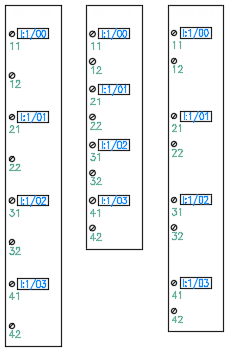
The PLC database contains the stack sequence and text values to annotate onto each symbol in the stack. As AutoCAD Electrical toolset builds the module, it reads the underlying ladder rung spacing and spreads out the stack or compresses it to match the rung spacing. During the insertion process, you can interrupt it to break the module and then restart it at a different location.
When you select a PLC module to insert, the program uses the PLC database information to:
- Select the appropriate symbols to use
- Stack them together in the order defined
- Draw a rectangle around it
- Create it as a single block
- Annotate the attributes
The parametric process uses a small set of library symbols to generate the stack sequence. The parametric PLC file names begin with the characters "HP" (Horizontal ladder rungs) or "VP" (Vertical ladder rungs). This is followed by a digit that corresponds to a PLC I/O style number. There are five predefined PLC styles provided with AutoCAD Electrical toolset, numbered 1 through 5.
Here is the same module generated using the five predefined styles.
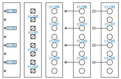
You can create your own style if your specific requirements are not met by any of the predefined styles. The program supports up to nine styles.
Full Units
Some PLC units may not lend themselves well to parametric generation. A PLC module can be inserted as a pre-built full unit if it uses the appropriate attributes and the block name begins with "PLCIO". The selected unit inserts into the ladder, breaks the wires, and then reconnects. A few sample full-unit PLC modules are supplied with the program.
Single, Stand-alone PLC Symbols
PLC I/O points can be inserted as independent symbols spread out over your drawing set. AutoCAD Electrical toolset provides a small set of single I/O point library symbols that you can expand and modify to suit your needs.
The symbols do not follow the normal AutoCAD Electrical toolset naming convention. Their file names must start with "PLCIO" in order for AutoCAD Electrical toolset to find and process them in the various PLC reports. The rest of the characters do not follow any naming convention.
Here are the file names of the default symbols:
|
PLCIOI1T.dwg |
First input, single wire left |
|
PLCIOI1.dwg |
2+ input, single wire left |
|
PLCIOI2T.dwg |
First input, wire left, and right |
|
PLCIOI2.dwg |
2+ input, wire left, and right |
|
PLCIOO1T.dwg |
First output, wire right |
|
PLCIOO1.dwg |
2+ output, wire right |
|
PLCIOO2T.dwg |
First output, wire left, and right |
|
PLCIOO2.dwg |
2+ output, wire left, and right |