Insert additional components.
Now you insert a system reset push button, pilot light, and an emergency stop push button to make up the circuit.
Insert a system reset button
- Click
 . Find
- In the Insert Component: JIC Schematic Symbols dialog box, click Push Buttons.

- In the JIC: Push Buttons dialog box, click Push Button NO.

- Respond to the prompts as follows:
Specify insertion point:
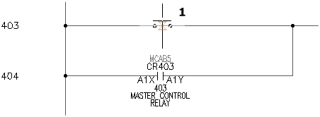
Position the push button on the wire at line reference 403 near the hot wire and click (1)
- In the Insert/Edit Component dialog box, verify the following:
Component Tag: PB403
AutoCAD Electrical toolset automatically assigned the tag name based on the line reference.
- In the Descriptions section, specify:
Line 1: SYSTEM
Line 2: RESET
- In the Location code section, click Drawing.
- In the All Locations - Drawing dialog box, select OPSTA3 and click OK.
- In the Insert/Edit Component dialog box, click OK.
Insert a pilot light
- Click
. Find
- In the Insert Component: JIC Schematic Symbols dialog box, click Pilot Lights.

- In the JIC: Pilot Lights dialog box, click Green Press to Test.

- Respond to the prompts as follows:
Specify insertion point:
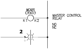
Position the pilot light on the wire at line reference 404 near the neutral wire and click (2)
 Tip:
Tip:Having Snap turned on makes positioning the pilot light easier.
- In the Insert/Edit Component dialog box, verify:
Component Tag: LT404
- In the Descriptions section, specify:
Line 1: CONVEYOR
Line 2: ON
- In the Location code section, click Drawing.
- In the All Locations - Drawing dialog box, select OPSTA3 and click OK.
- In the Insert/Edit Component dialog box, click OK.
Insert a push button for emergency stop
- Click
. Find
- In the Insert Component: JIC Schematic Symbols dialog box, click Push Buttons.
- In the JIC: Push Buttons dialog box, click Mushroom Head NC.

- Respond to the prompts as follows:
Specify insertion point:
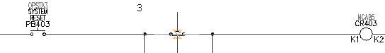
Position the push button on the middle of the wire at line reference 403 and click (3)
- In the Insert/Edit Component dialog box, verify:
Component Tag: PB403A
AutoCAD Electrical toolset automatically assigned the tag name based on the line reference. It added the “A” suffix since it is your second push button on this line reference.
- In the Descriptions section, specify:
Line 1: EMERGENCY STOP
- In the Location code section, click Drawing.
- In the All Locations - Drawing dialog box, select OPSTA3 and click OK.
- In the Insert/Edit Component dialog box, click OK.
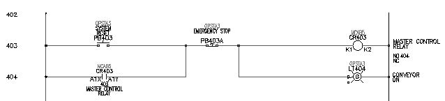
Your finished schematic resembles the following: