Use the Insert Wire tool to insert lines that represent pipes on a hydraulic drawing.
In AutoCAD Electrical toolset, different types of wires represent the type of running pipes that allow water or oil flows from one instrument to another. Start by setting up the type of wires for pipe runs.
Insert wires as pipes
- Click
 . Find
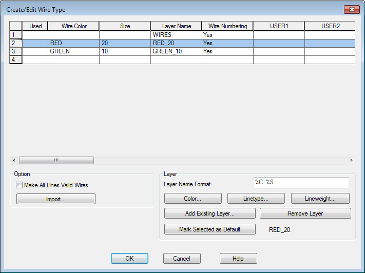
- In the Create/Edit Wire Type dialog box, specify:
Wire Color: RED
Size: 20
The Layer Name is automatically created. The name RED_20 is assigned to the wire layer you are creating.
- Click Color.
- In the Select Color dialog box, select red and click OK.
- Click Linetype.
- In the Select Linetype dialog box, select Continuous and click OK.
- In the Create/Edit Wire Type dialog box, specify:
Wire Color: GREEN
Size: 10
Color: Green
Linetype: Hidden2
Note: If HIDDEN2 is not available, click Load. Select it from the list of line types on the Load or Reload Linetypes dialog box. - Select RED_20 in the grid and click Mark Selected as Default.
- Click OK.
- Click
. Find
- Respond to the prompts as follows:
Specify wire start or [wireType/X=show connections]:
Enter X and press ENTER
Specify wire start or [wireType/X=show connections]:
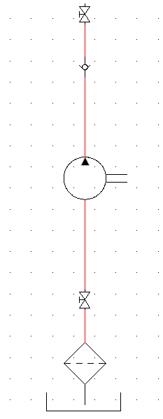
Select the bottom of the shut off valve
Specify wire end or [Scoot/T=wiretype, X=show connections]:
Select the top of the check valve
- Continue inserting wires connecting the components together. Right-click to exit the command.
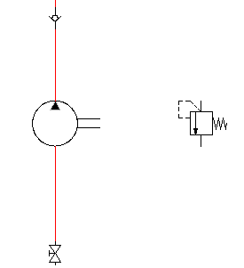
Your drawing should look like the following:
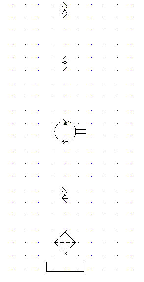
 Note: You can also insert the vertical or horizontal pipes first and then insert the components onto the pipe, one at a time.
 - Click
 . Find
- In the Insert Component: Hydraulic Symbol dialog box, select the check box for Vertical.
- In the Insert Component: Hydraulic Symbol dialog box, click Pressure Relief Valves.

- In the Hydraulic: Pressure Relief Valves dialog box, click N.C. Pressure Relief Valve with Preset -1.

- Respond to the prompts as follows:
Specify insertion point: Select to place the valve to the right of the pump
- In the Insert/Edit Component dialog box, specify:
Component Tag: VAL4
Description: Line 1: Pressure Relief
Click OK.
- Click
. Find
- Respond to the prompts as follows:
Specify wire start or [wireType/X=show connections]:
Enter X, pressENTER
Specify wire start or [wireType/X=show connections]:
Press SHIFT + right-click and select Midpoint from the menu, then select the midpoint on the pipe between the pump and the shut off valve above it
Specify wire end or [V=start Vertical/H =start Horizontal/Continue):
Drag the pipe to the right so that it is directly above the pressure relief valve. Drag the pipe down and click the top connection point on the pressure relief valve
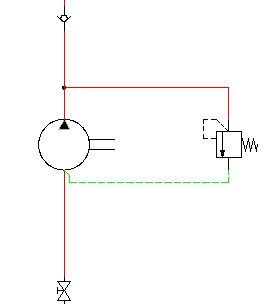
You now insert a pipe that connects the end of the valve back to the pump.
Specify wire start or [wireType/X=show connections]:
Enter T, pressENTER
Select the wire layer GREEN_10. Click OK.
Tip: Make sure that Snap is turned off and that the Wire Layer is set to GREEN_10.Select the bottom connection point on the pump
Specify wire end or [V=start Vertical/H =start Horizontal/Continue):
Drag the pipe down and to the right, click the connection point at the bottom of the pressure relief valve, right-click