AutoCAD Mechanical toolset provides 11 types of symbols to insert into a drawing.
The supported symbols are:
- Datum identifier symbols
- Datum target symbols
- Edge symbols
- Feature control frame symbol
- Feature identifier symbols
- Leader note symbols
- Taper and slope symbols
- Surface texture symbols
- Welding symbol
- Marking/Stamping symbol
- Dead joint symbol
Symbols and the Drafting Standard
The drafting standard defines the behavior and characteristics of each symbol. To change the characteristics, you edit the elements of the standard. You access elements of the standard in the AM:Standards tab in the Options dialog box.
Common Characteristics
Attach behavior
While creating a symbol, you can attach it to an object. Thereafter, when you move the object, the symbol moves with it.
Symbols can get detached from an object when the point of attachment is no longer valid. For example
- If a symbol is attached to a block reference, and the block is redefined, and the attachment point moves.
- If a symbol is attached to model documentation drawing view geometry, and an update or edit event causes the leader attachment point to disappear.
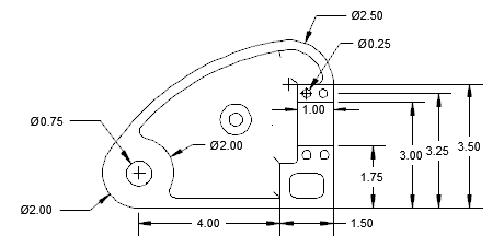
Before update event
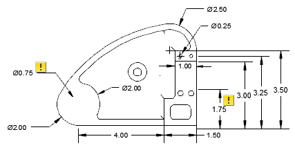
After update event
If the annotation monitor is on, it tracks annotations that are detached and highlights the detached annotations with a badge. Clicking the badge displays a menu that contains options specific to that annotation.
Leader creation behavior
If you attach a symbol to an arc or spline, the symbol forces the first leader segment to be perpendicular to the attached object. You can override this behavior by pressing the Toggle Symbol Leader Orthogonal Mode key (SHIFT + F, by default) as you move the crosshairs.
If you attach a symbol to a line, some symbols force you to make the first leader segment perpendicular to the attached object. For symbols that do not show this behavior, if you turn on Object Snap Tracking, AutoCAD Mechanical toolset displays perpendicular alignment paths to track to them.
Leader start point grip edit behavior
If you drag the start point of a leader, the entire symbol moves.
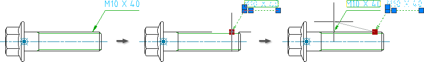
You can override this behavior by pressing the Toggle Symbol Leader to Stretch Mode key (SHIFT + G, by default) as you move the crosshairs. In this mode the symbol does not move. Instead, the first leader segment stretches.
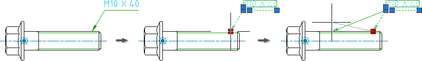
- Datum Identifier symbols (because they allow the first leader segment to be stretched by default).
- Datum Target symbols (because drafting standards specify that the first leader segment must always be perpendicular to the attached object).
Symbol libraries
Some symbols let you save fully configured symbols to a library. You can then directly insert them in a drawing from the ribbon, eliminating the need to specify values, or only specify the values that are from the saved symbol.
Edit Symbols
To edit symbol text of a symbol that is already inserted in a drawing, double-click the symbol. Double-clicking the leader displays the Leader tab of the symbol’s settings dialog box.
Summary
| Symbol | First leader segment perpendicular to attached arc | First leader segment perpendicular to attached line | Symbol Library | Tracked by Annotation Monitor? | SHIFT+G Support |
|---|---|---|---|---|---|
|
Datum Identifier |
Yes | Yes | Yes | ||
|
Datum target |
Yes | ||||
|
Edge |
Yes | Yes | Yes | Yes | |
|
Feature control frame |
Yes | Yes | Yes | Yes | Yes |
|
Feature identifier |
Yes | Yes | Yes | Yes | |
|
Leader note |
Yes | Yes | Yes | Yes | |
|
Taper and slope |
Yes | Yes | Yes | ||
|
Surface texture |
Yes | Yes | Yes | Yes | |
|
Welding |
Yes | Yes | Yes | Yes | |
|
Marking/Stamping |
Yes | Yes | Yes | Yes | |
|
Dead joint |
Yes | Yes | Yes | Yes |