-
Click

 Edge Symbol . Find
Note:
Edge Symbol . Find
Note:Only the DIN, GB, JIS, and ISO standards support edge symbols.
- Select the object you want to attach the symbol to.
- If you attached the symbol to a line, in the drawing area, specify the start point for the leader.
If you attached the object to an arc, circle, ellipse or spline, skip to the next step.
- Specify the second point of the edge symbol leader and press ENTER. Tip:
- If the symbol is attached to an arc, circle or line: To allow non-perpendicular leaders, press the Toggle Symbol Leader Orthogonal Mode key (SHIFT + F, by default) as you drag the crosshairs.
- If the symbol is attached to a line: To make the first leader segment perpendicular to the attached line, move the cross hairs so that the leader is approximately perpendicular, and track along the alignment path that is displayed.
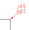
- In the Edge Symbol dialog box, specify the edge symbol requirements.
- To insert an edge symbol without specific data, select Allow undefined size and click Burr or passing permitted, or Undercut required. To define the direction, select from the drop-down list.
- To set the edge symbol data, enter the Edge symbol value in the upper or lower box in the parameters area or select the value from the drop-down list.
- To display the standard revision next to the symbol, select Show Standard Label.
- To add the all-round designation, click the All-round button.
- Click OK.