Use this dialog box to specify which adjustment methods to display in the Traverse Adjustment dialog box, which method is the default, and the colors to use to display the results in the dialog box and in the drawing. You can also use this dialog box to specify how curve data is treated when adjusted.
Adjustment Methods
-
Specifies the adjustment methods to display in the Traverse Adjustment dialog box, the default adjustment method, and the colors to use for each method when displaying the results in the dialog box and in the drawing.
- Compass: A method of corrections where the closing errors are assumed to be as much due to errors in observed angles as by the errors in measured distances. The closing errors in latitude and departure are distributed according to the ratio of the length of the line to the total length of the traverse.
- Transit: A method of balancing a traverse where the closing errors are assumed to be caused less by the errors in the observed angles than by the errors in measured distance. Corrections are distributed according to the ratio of the latitude and departure of each leg of the traverse to the sums of the latitude and departures of the entire traverse.
- Crandall: A method of balancing a traverse where all the angular error is distributed throughout the traverse and all adjustments to the traverse are due to modifying the traverse distances. The modification distance made to each leg is such that the sum of the squares is a minimum. Corrections corresponding to the closing errors assume that the closing errors are random and normally distributed, and that all the angular error has been adjusted prior to the adjustment routine.
-
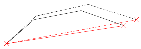
Grant Line: Used for open traverses only. Scales and rotates the traverse based on the line that is defined by the start point and the point of closure that you specify in the Traverse Adjustment dialog box.
In the following illustration, the original traverse is a solid black line, and the traverse adjusted with the Grant Line method is a dashed black line. The red lines are not part of the traverse but are reference lines to show the rotation and scale adjustments.

- Angular: Specifies the color to use for displaying the angular balance results in the Traverse Adjustment dialog box.
Adjust Curves
This setting defines how curve data in a traverse is represented for adjustment. Curves themselves cannot be adjusted, so lines are added into the traverse to represent the curves, and the curves are removed. You can specify whether the lines are added across the chords, or whether they are added at the curve PIs.
- Across Chord
- Creates a line across the chord of the curve.

When you select this method, sides that represent the curves are listed as "<side number> Arc" in the Traverse Adjustment dialog box.
- At PI
- Adds lines that intersect at the curve PI.

- Extend Tangents to PI
- Specifies whether adjacent tangent sides of the traverse are extended to the curve PIs, consolidating the sides.
- When the
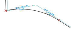
Extend Tangents to PI check box is selected, sides that represent the curves are consolidated with adjacent sides if they are tangent to the curves. In the following illustration, the side that represents the curve from the PI to the PT is consolidated with the adjacent side in the traverse. Dimensions are used in the illustration to represent the resulting sides.

The sides that are consolidated are listed with their consolidated components, such as "<side number> Arc 2 - Line" for example, in the Traverse Adjustment dialog box.
- When the
Extend Tangents to PI check box is cleared, sides that represent the curves are not consolidated with adjacent tangent sides. In the following illustration, the side that represents the curve from the PI to the PT is not consolidated with the adjacent side in the traverse. Dimensions are used in the illustration to represent the resulting sides.

The sides that represent the curves are listed as "<side number> Arc 1" and "<side number> Arc 2", for example, in the Traverse Adjustment dialog box.
- When the
Extend Tangents to PI check box is selected, sides that represent the curves are consolidated with adjacent sides if they are tangent to the curves. In the following illustration, the side that represents the curve from the PI to the PT is consolidated with the adjacent side in the traverse. Dimensions are used in the illustration to represent the resulting sides.