You can position a UCS relative to the origin or to existing geometry, align sketch geometry with a UCS, measure the distance of a UCS, redefine a UCS, or specify UCS document settings.
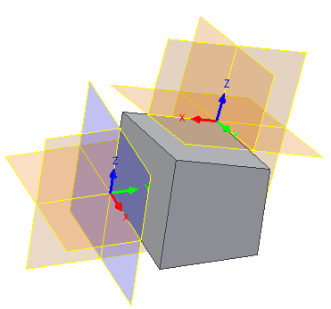
Position a UCS Relative to the Origin
- Click 3D Model tab
 Work Features panel UCS
  .
. - Click the axes to move the UCS in the desired direction. Click the arrowheads to rotate the UCS.
- Right-click and choose Finish.
Position a UCS Relative to Existing Geometry
- Click 3D Model tab Work Features panel UCS .
- Specify a point to select the direction of the X axis.
- Specify a point to select the direction of Y axis.
Align Sketch Geometry With a UCS
You can select the UCS triad as an input for 2D Sketch command. You can also use the UCS work features for 2D Sketch.
The origin of the sketch is aligned with the UCS center point, and the center point is projected to the sketch.
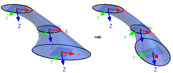
If the UCS position changes (either because its parameters or target geometry changed, or because the UCS was redefined), the sketch is updated.
Measure Distance of a UCS
If a part or assembly file contains a UCS, the Measure Distance dialog box offers UCS options in its menu.
- On the ribbon, click Tools tab Measure panel Distance.
- In the Measure Distance dialog box, click the drop-down menu and:
- Select Origin to show distance from an Origin of the part.
- Select a desired UCS to show distance from the origin of the specified coordinate system.
Redefine a UCS
- Do either of the following:
- Double-click the UCS.
- Select UCS, right-click, and choose Redefine Feature.
- Do any of the following:
- Specify the UCS position relatively to the Origin, or, in a part file, also relative to the existing geometry.
- Click the UCS triad origin and move the UCS to a new location.
- Click the axis to rotate the triad around the selected axis.
- Click the arrowhead to move the triad along the selected axis.
Specify UCS Document Settings
- Click Tools tab Options panel Document Settings.
- In the Modeling tab of the Document Settings dialog box, in the User Coordinate System area, click Settings.
- In the UCS Settings dialog box, specify any of the following:
- Naming Prefix. Sets the UCS prefix. UCS name is generated from this prefix and a numeric index.
- Default Plane. Select the default 2D sketch plane. Affects the behavior of 2D Sketch and View Face commands, when UCS triad is selected as an input.
- Visibility. Select the visibility of UCS objects.