UCS (user coordinate system) is a collection of work features (three workplanes, three axes, and a center point).
Unlike Origin, there can be multiple UCS in a document, and you can place and orient them differently.
When you create or modify objects in a 3D environment, you can move and reorient the UCS in 3D model space to simplify your work.
Work features in UCS can be used to place sketches and features that update when the UCS is redefined.
In a part file, you can position UCS relatively to existing geometry by selecting three points, or relatively to the Origin.
In a part file, UCS placement supports the following inputs as points:
- Point (vertex of solid edge, midpoint of solid edge, sketch, or work point origin)
- Solid circular edge or solid elliptical edge
In an assembly file, you can position UCS relatively to the Origin but you cannot position UCS relatively to existing geometry. When placing UCS in an assembly, you can select a point, but the UCS is still placed in absolute coordinates and not related to the point!
You can use UCS for measurements, and its work geometry can be included in the drawing.
The UCS triad can be selected for the View Face command.
Define the UCS Location
You can define a UCS in the following ways:
- Specify a new origin (one point), new X axis (two points), or new XY plane (three points).
- Align the UCS by selecting a face on a 3D solid object. The selection can be on a face or on an edge of the solid.
- Rotate the current UCS around any of its three major axes.
UCS browser
UCS triad is represented with a triad icon in the browser. Similar to the Origin, the UCS node owns its work geometry nodes.
If you place multiple occurrences of a UCS, they are incrementally numbered and displayed in the order they were inserted. In a part file, drag to reorder them in the browser.
Set the default UCS prefix in the UCS Settings dialog box. You cannot change the name of UCS work features (center point, planes, axes), their names are dependent on the UCS name.
If you position UCS relatively to existing part geometry, Show Inputs option is available in the context menu.Click to highlight the geometry from which UCS was created.
UCS context menu
During UCS edit, right-click in the graphics window to display the UCS context menu:
- Finish
-
Inserts UCS in the specified location. When selecting geometry placement, select origin, X axis, and Y axis to place UCS.
- Restart
-
Restarts the UCS command.
- Done [Esc]
-
Cancels the UCS command, no UCS is inserted.
- Back
-
Reverses the most recent selection.
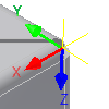
What do the colors refer to on the UCS triad?
Because you can rotate the UCS triad, the colors help you identify axes. The colors correspond to the default colors of the principle part axes:

- Red is the X axis.
- Green is the Y axis.
- Blue is the Z axis.
If you customize system colors or the UCS triad colors, the colors might not match the part axes.
What do the UCS triad segments mean?
When placing the UCS, the mouse cursor changes according to what you select in the triad. Click a triad segment or drag to indicate the type of transform you want. You can drag or enter precise coordinates or angles corresponding to your selection.
![]() Select triad segment to define type of transformation.
Select triad segment to define type of transformation.
![]() Click the UCS origin to change its position. Drag the origin to desired location to change its position.
Click the UCS origin to change its position. Drag the origin to desired location to change its position.
![]() Click the arrowhead to move the UCS triad along the axis.
Click the arrowhead to move the UCS triad along the axis.
![]() Click the axis to rotate the triad around the selected axis. Or, specify a point for XY plane when selecting part geometry.
Click the axis to rotate the triad around the selected axis. Or, specify a point for XY plane when selecting part geometry.
![]() Select a point to specify a direction for X axis.
Select a point to specify a direction for X axis.
Heads Up Display (HUD)
As you move the cursor over the UCS selection location, the HUD provides feedback and cues about each possible selection. There is a box where you can enter precise values.
Use the TAB key to move between boxes where you set the values for UCS coordinates, or angle of rotation.
When you place UCS absolutely and UCS faces the same direction as global axis, Heads Up Display coordinate values for UCS origin are absolute. Heads Up Display rotation values are relative to the current UCS orientation, and start with the zero value.
When you redefine UCS positioned relatively to existing geometry, Heads Up Display coordinate values for are absolute.
The HUD can contain:
- A prompt for the expected inputs.
- Relative or absolute flag for the input value.
- Description of the input.
- Edit field for the input value. You can manually enter the position of UCS origin. When you enter a value for X, Y, or Z axis, the edit field is locked. You can return or move between edit fields using the TAB key.
UCS parameters
Each UCS defines six parameters - three positional coordinates, and three coordinates to drive the rotation angles.
If you position UCS absolutely, the parameter values are absolute.
If you place UCS on existing geometry, the coordinates and rotations are relative to the target geometry, so after the initial placement, the parameter values are set to 0. If you redefine the UCS to offset its position, the parameters reflect the relative transformation.
UCS visibility
Each of the UCS work features shows a visibility state in the browser.
Set the default visibility of UCS triad and its work features in the UCS Settings dialog box. You can modify visibility of individual UCS work features independently.
You can also set the visibility of work features in your active part or assemblyfile. Select View tab  Visibility panel Object Visibility . For UCS, you can set visibility to UCS triad, UCS planes, UCS axes, and UCS points.