Insert, merge, crease or match edges, or insert points.
Important: The Freeform panel is converted to a ribbon tab when you are working in the freeform environment.
Insert Edges
Insert edges to add more control in specific areas.
- Click Freeform tab
 Modify panel Insert Edge
  .
. - Use the Edges selector to select edges in the graphics window. Tip: Double-click an edge to select the edge loop. Use Ctrl-click or Shift-click to add or remove edges.
- In the Insert Edge dialog box, enter the Location. The Location specifies the position of the new edges using a decimal percentage. The Location must be between -1 and 1. Tip: Use a negative number to reverse the insertion side of the edges.
- Specify the insertion Mode:
- Simple. Adds the edges you specify which may alter the shape.
- Exact. Adds the edges you specify and extra edges to maintain the current shape.
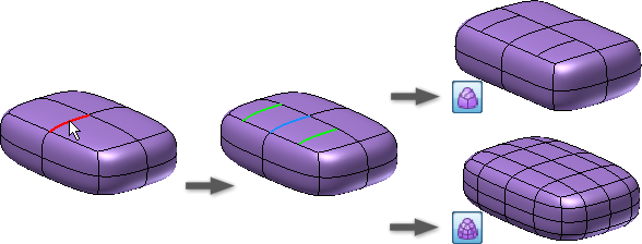
- Specify the insertion Side:
- Single. Inserts on a single side of the selected edges.
- Both. Inserts edges on both sides of the selected edges.
- Select OK .
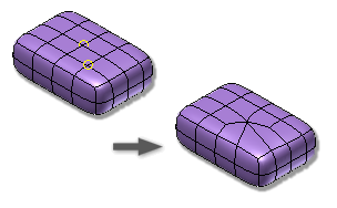
Insert Points
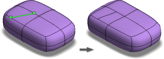
Insert points to add edges within the specified face.
- Click Freeform tab Modify panel Insert Point
 .
. - Use the Points selector to select edges or vertices in the graphics window.
- Specify the insertion Mode:
- Simple. Adds the edges to the selected faces which may alter the shape.
- Exact. Adds the edges you specify and extra edges to maintain the current shape.
- Select OK .
Merge Edges
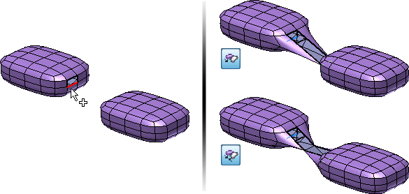
Merge edges to join open freeform edges.
- Click Freeform tab Modify panel Merge Edges
 .
. - Select Set 1 open edges in the graphics window.
- In the dialog box, change the focus to Set 2 and then select the Set 2 open edges in the graphics window.
- Set the Mode.
- Use To Edge to blend to the second edge selection.
- Use To Middle to blend to the midpoint of the two edge selections.
- Select OK.
Match Edges
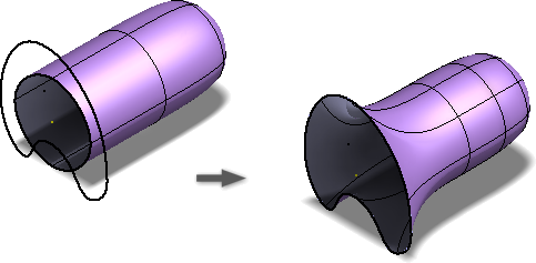
Use Match Edge to modify the freeform body to match to existing model or sketch geometry.
For example, to create a lid for a coffee pot, the boundary of the lid must match the boundary of the pot. First, use the various freeform commands to create the approximate shape for the lid. Next, use the Match Edge command to match the edges of the freeform lid body to the boundary curves of the coffee pot model.
Important: If the source boundary curves change, expand the Matches folder in the browser and select Rematch or Redefine in the context menu.
- Click Freeform tab Modify panel Match Edge
 .
. - The Edges option is active in the dialog box. On the freeform body, select one or more freeform edges to modify. Double-click an edge to select a loop.
- In the dialog box, click Target. In the graphics window, select the model or sketch curves for the selected freeform body edges to conform to.
- If the match solution is twisted, use Flip Direction to remove the twist.
- If desired, enable Target Chain to select the target edge chain directly.
- Specify the Tolerance for the edges and the matching curves:
- Requested. Enter the desired tolerance value for the selection.
- Achieved. Passive display of the actual tolerance for the selection.
- Optionally, if the match edge is a NURB surface edge, you can set the Continuity.
- Select Position for G0.
- Select Tangent for G1 and then specify the Tangent scale if desired.
- Select Curvature for G2 and then specify the Tangent and Curvature scale if desired.
- Click OK.
- Optionally, if the source boundary curve changes:
- In the browser, expand the Matches folder.
- Right-click the matched edge and select Rematch or Redefine.
Tips for Using Match Edge
- Edit the freeform model to be as close as possible to the final shape before creating the match.
- After completing the Match command, use Edit Form to remove portions of the freeform body that extend beyond what is required.
- For closed loops, Match works best when the curves turn in the same direction.
- When you are trying to create a box, avoid using loops around the end.
- Avoid using Match with sharp corners. The resulting model has a crease that Inventor can’t shell or thicken.
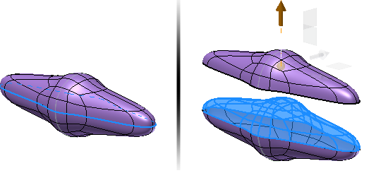
Weld Vertices
Use Weld Vertices to join two or more vertices.
- Click Freeform tab Modify panel Weld Vertices
 .
. - Do one of the following:
- Select Vertex to Vertex to merge two vertices. Select two vertices. The first vertex is moved to the position of the second vertex.
- Select Vertex to Midpoint to move two vertices to the midpoint between the selections. Select two vertices.
- Select Weld to Tolerance to combine multiple vertices within a specified tolerance. Select the vertices and then set the Tolerance value. Tip: You can use a crossing window to select vertices with this option.
- Select OK.
Unweld Edges
Use Unweld Edges to disconnect edges and loops in freeform shapes.
- Click Freeform tab Modify panel Unweld Edges
 .
. - Select at least two edges to unweld. Double-click an edge to select a loop.
- Select OK.
Tip: Use Edit Form to separate two halves of an unwelded loop.
Crease Edges
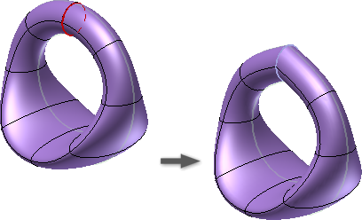
Use Crease Edges to create a sharp crease on the selected edges.
- Click Freeform tab Modify panel Crease Edges
 .
. - Select the freeform edges to crease.
- Select OK.
Uncrease Edges
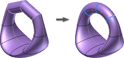
Use Uncrease Edges to remove a crease from the selected edges.
- Click Freeform tab Modify panel Uncrease Edges
 .
. - Select the Creased Edges to uncrease.
- Select OK.
Note: Only creased edges are selectable for an uncrease operation.