The Thicken/Offset command lets you add or remove thickness to faces of a part or a quilt, create an offset surface from a part face or surface, or create a new solid.
What's New: 2021
Thicken Workflows
- Click
3D Model tab
 Modify panel
Thicken/Offset
Modify panel
Thicken/Offset
 .
.
- To the right of the Breadcrumb, specify the output type: Solid
 .
.
- Specify the
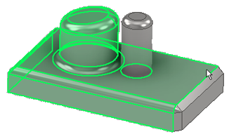
Input Geometry. Click Select Faces and select existing faces or surfaces.
Tip: To select multiple tangent continuous faces to thicken, select Automatic Face Chain. All selected faces thicken with the same Boolean operation and direction.
- In the
Behavior section, specify...
- Direction: choose from Inside
 , Outside
 , or Center
 .
.
- Distance: specify the thickness or distance of the offset.
If needed, click the arrow to use the Measure command, Show dimensions, or select a recently used value.
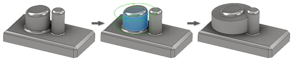
- Automatic Blending: as shown below, this option automatically moves adjacent tangential faces and also creates new blends if required. It is available when solid faces are selected for a Thicken operation and when the thickness extends in the positive or negative direction, but not when you’re thickening equally in both directions.
Automatic Blending OFF:
 Automatic Blending ON:
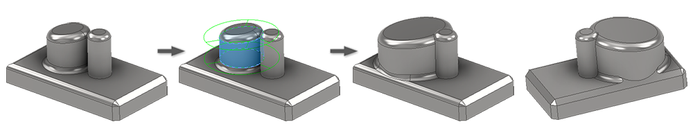
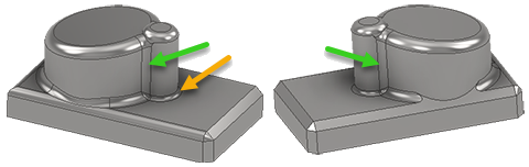
Notice the smaller cylinder doesn't have a fillet at its base. This limits the extent of the blend that is created. To get a blend into the smaller cylinder place a fillet between it and the feature at its base. The blend fillet uses the fillet radius at the base of the Input Geometry.
- Direction: choose from Inside
- In the
Output section, not available when using Automatic Blending, specify the results:
 Join. Adds the volume created by the Thicken feature to the solid part.
 Cut. Removes the volume created by the Thicken feature from the solid part.
 Intersect. Creates a new feature from the shared volume of the Thicken feature and the solid part. Material not included in the shared volume is deleted.
 New Solid. Creates a new solid body. This is the default selection if the thicken operation is the first solid feature in a part file. Select to create a new body in a part file with existing solid bodies. Each body is an independent collection of features separate from other bodies. A body can share features with other bodies. If desired, rename the body.
Solids: Displays when there is more than one solid body in the file, click the selector and select the participating body.
Boolean (Solids)
- In the
Advanced Properties section, specify whether and how to calculate approximations:
- Allow Approximation. When no precise solution exists, allows a deviation from the specified thickness while computing the offset feature. A precise solution creates an offset surface where each point on the original surface has a corresponding point on the offset surface. The distance between these two points is the specified distance.
- Mean. If approximation is allowed, deviation is divided to fall both above and below the specified distance.
- Never Too Thin. If approximation is allowed, preserves minimum distance. The deviation must fall above the specified distance.
- Never Too Thick. If approximation is allowed, preserves maximum distance. The deviation must fall below the specified distance.
- Tolerance as Optimized. Computes approximation using a reasonable tolerance and minimal compute time.
- Tolerance as Specified. Computes approximation using the tolerance you specify. Valid tolerance range is from 0-100. Considerable compute time may be required.
- On the More tab, if desired, select Create Vertical Surfaces.
Create Vertical Surfaces creates vertical or “side” faces connecting the offset faces to the original quilt. Vertical surfaces are created only at internal surface edges, not at boundary edges of surfaces.
Note: You can’t create vertical surfaces to join an offset surface to a solid part. - Click OK to create the feature or Apply to create and continue with additional thicken features.
Offset Workflows
- Click
3D Model tab
Modify panel
Thicken/Offset
.
- To the right of the Breadcrumb, specify the output type: Surface
 .
Note: Offset surfaces do not add or remove mass.
.
Note: Offset surfaces do not add or remove mass. - Specify the
Input Geometry. Click the Faces selector and select existing solid faces or surfaces.
Tip: Use the
 Quilt selection option, for surfaces only, to select a group of connected surfaces with one click. When you toggle this option it clears the selection set.
Tip: Use Automatic Face Chain to select multiple tangent continuous faces to offset. All selected faces are offset with the same Boolean operation and direction.
Quilt selection option, for surfaces only, to select a group of connected surfaces with one click. When you toggle this option it clears the selection set.
Tip: Use Automatic Face Chain to select multiple tangent continuous faces to offset. All selected faces are offset with the same Boolean operation and direction. - In the
Behavior section, specify...
- Direction: choose from Inside
, Outside
, or Center
.
- Distance: specify the offset distance.
If needed, click the arrow to use the Measure command, Show dimensions, or select a recently used value.
Note: You can create copies of surfaces with a zero distance offset, but not surfaces with vertical sides. This can be useful when you want to make a copy of an entire surface body or a set of individual faces from any solid model or surface.
- Direction: choose from Inside
- In the
Output section, specify:
 Move surface. Moves an existing surface including creating side surfaces to connect the offset surfaces with the original quilt. Side surfaces are created only at internal surface edges, not at boundary edges of surfaces.
Note: You can’t create side surfaces to join an offset surface to a solid part.
Move surface. Moves an existing surface including creating side surfaces to connect the offset surfaces with the original quilt. Side surfaces are created only at internal surface edges, not at boundary edges of surfaces.
Note: You can’t create side surfaces to join an offset surface to a solid part. New surface. Creates an offset surface at the specified distance.
- In the
Advanced Properties section, specify whether and how to calculate approximations:
- Allow Approximation. When no precise solution exists, allows a deviation from the specified thickness while computing the offset feature. A precise solution creates an offset surface where each point on the original surface has a corresponding point on the offset surface. The distance between these two points is the specified distance.
- Mean. If approximation is allowed, deviation is divided to fall both above and below the specified distance.
- Never Too Thin. If approximation is allowed, preserves minimum distance. The deviation must fall above the specified distance.
- Never Too Thick. If approximation is allowed, preserves maximum distance. The deviation must fall below the specified distance.
- Tolerance as Optimized. Computes approximation using a reasonable tolerance and minimal compute time.
- Tolerance as Specified. Computes approximation using the tolerance you specify. Valid tolerance range is from 0-100. Considerable compute time may be required.
- Click OK to create the feature or Apply to create and continue with additional thicken features.