Important: The Freeform panel is converted to a ribbon tab when you are working in the freeform environment.
Subdivide a Freeform Face
Subdivide splits existing faces into two or more faces providing more control and detail to the freeform body.
- Click Freeform tab
 Modify panel Subdivide
  .
. - Use the Faces selector to select faces in the graphics window. Tip: Ctrl-click to add faces. Shift-click to remove faces.
- In the Subdivide dialog box, specify the number of Faces you want for the Width and Height.
- Specify the insertion Mode:
- Simple. Adds only the number of faces specified. The overall shape may change.
- Exact. Adds extra faces to adjacent areas to preserve the current shape.
- Click OK.
Bridge Freeform Faces
The Bridge command connects bodies or creates holes in a freeform model. Editing a freeform body with Bridge allows you to develop smooth connections by specifying faces or edges to bridge.
In the following image, faces are selected to bridge the gap between two bodies. 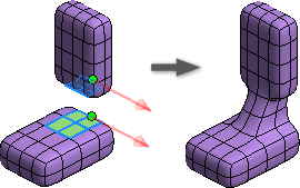
In the next example, edges are selected to bridge the gap between two bodies. 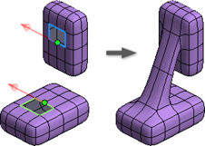
In the last example, faces are selected on opposite sides of the same body to create an opening. 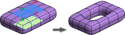
- Click Freeform tab Modify panel Bridge
 .
. - Use the Side1 selector to select the start faces or edges for your bridge.
- Use the Side2 selector to select end faces or edges for your bridge.
- (Optional) Click Flip to reverse the direction around the loops. Alternately you can select an edge near an arrow to flip the direction.
- Specify the number of Faces to create between side one and side two.
- Specify the number of Twists (complete rotations of the bridge) between side one and side two.
- Click OK.
Tip: Inventor can switch the selectors without user interaction based on your selections.
Tips for Bridging Freeform Faces
- Provide a larger number of faces if the bridge includes twists.
- You can pick points to align the bridge to by selecting a vertex on each loop. The vertices provide the orientation of the bridge. If there is only a single face span, then the two vertices connect by a single edge. The arrows show the direction around the loops. The flip buttons reverse the direction around the loops.
Thicken Freeform Faces
The Thicken command does the following:
- Converts an open surface to a solid with soft or sharp edges.
- Creates an offset surface.
- If the selected freeform body is a solid, creates an interior or exterior shell wall.
- Click Freeform tab Modify panel Thicken
 .
. - Use the Body selector to select the body in the graphics window. A single body is selected automatically.
- If the selected body is a solid, the following options are not available. If the selected body is a surface, set the Type and Direction:
- Select Sharp to convert a surface to a solid body with acute edges. Creases on boundary edges are retained.
- Select Soft to convert a surface to a solid body with round edges. Creases on boundary edges are removed.
- Select No Edge to create an offset surface.
- Specify the Thickness value to:
- Set the shell wall thickness for a solid body.
- Set the thickness of a surface converted to a solid.
- Set the offset surface distance if the No Edge option is specified.
- Optionally choose Flip Direction if desired.
- Specify the Direction.
- Select Normal to thicken perpendicular to the selection.
- Select the Axis option and then pick an axis in the browser or graphics window to specify the thicken direction. Valid axis selections include:
- Work axis
- Linear BREP edge
- Planar BREP face
- Work plane
- Linear 2D or 3D sketch curve
- Click OK.