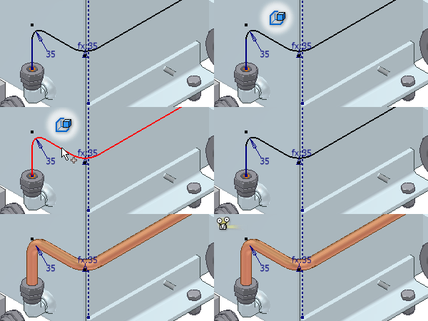
A derived route is created based on a 3D sketch in the assembly. A base sketch can be created based on geometry in any part that exists in the standard Autodesk Inventor assembly or tube and pipe runs assembly. It must be outside any routes. Using 3D sketches to create derived routes, the resultant derived routes contain exactly the same geometry as selected from the base sketch.
3D sketches can be outside a part, for example, you may want to create separate sketch lines that are only parallel or perpendicular to geometry in the part. To make use of geometry in a part, apply constraints to a base sketch between sketch elements and geometry in the part. 3D constraints, such as Parallel and Perpendicular, are significant for orthogonal tube and pipe design systems. Valid base sketches include:
- Existing 3D sketches in the assembly.
- New 3D sketches you create based on useful geometry in the assembly.
General workflow for creating derived routes
- Use existing 3D sketches or create a new base sketch based on useful geometry in the assembly for tube and pipe design. Make sure that the base sketch is not consumed in any routes.
- Create the initial derived route.
- Edit the base sketch in the 3D Sketch environment to automatically update the selected sketch elements or allow for new sketch elements until you break the link between them.
- Add or remove sketch elements from the base sketch.
- Populate the derived route, and then modify the populated route as needed.
Which 3D sketch elements are valid selections for derived routes?
You can select sketch elements in a single base sketch only. You can select sketch lines and arcs in a base sketch to create derived routes. Splines are not a valid selection.
Use the context menu to choose any of the single, chain, and whole sketch selection:
- Single: Selects each valid sketch element individually.
- Chain: Selects the longest continuous sketch elements between any two adjacent branch points.
- Whole: Selects the whole 3D sketch for the derived route.
What is the relationship between a derived route and the base sketch?
Derived routes are linked with the associated base sketches by default. Include new geometry into the base sketch, and then select new sketch elements for the derived route. Geometry added to a base sketch is not automatically added to the derived route. You must edit the derived route and select the geometry to add it.
The following changes to the base sketch automatically update the derived route:
- Repositioning geometry that is selected into the derived route.
- Modifying dimensions of geometry that is selected into the derived route.
- Deleting geometry that is selected into the derived route.
To modify a derived route or the base sketch independently, break the link between them.
How does a derived route differ from a normal route?
|
|
A particular route icon in the Model browser indicates a derived route. They differ in the following aspects:
|
When the link between a derived route and the base sketch is broken, the derived route changes to a normal route, and the route icon in the Model browser changes.
How do derived routes respond to tube and pipe defer updates?
When editing a derived route that is set to defer updates, only the derived route sketch updates automatically. The derived route does not repopulate automatically when tube and pipe defer updates are enabled. A derived route that is newly created and populated always defaults to be displayed as populated. You can defer automatic updates for new derived routes at a later time. When editing a deferred derived route, only the derived route sketch automatically updates. The derived route does not repopulate until automatic updates are enabled.
Why are manual adjustments required to complete a derived route?
When there are violations against the minimum segment length, maximum segment length, or minimum bend radius of the style, you can do the following to correct the violation:
- Edit the part containing the base sketch.
- Edit the base sketch.
- Modify the tube and pipe style that is used to create the derived route.
When a derived route is populated, only conduit parts , couplings, and elbows are automatically generated and engaged using specified library parts from the Autodesk Inventor Content Center. At branch sketch points, especially where tees or crosses are required, or when the geometry selection is not continuous, pipe segments may overlap or fall apart from each other. In these cases you must place the correct fitting and make appropriate adjustments to the length of the pipe segment to get the correct engagement and complete the route. To get the correct engagement, you can:
- Modify the dimensions of sketch elements in the base sketch. Make sure the link between the derived route and the base sketch is not broken.
- Use Trim/Extend Pipe to modify free pipe ends.
What happens when you break the link between a derived route and the base sketch?
By default, the derived route is linked with the base sketch. Once you break the link:
- The derived route becomes independent so that base sketch edits can no longer affect the route.
- The route is a series of sketched route points and segments. Editing capabilities are available.