There are two types of rigid routes: the rigid pipe with fittings type and the bent tube type. Rigid piping routes can comprise pipe segments, couplings, standard 45 and 90-degree elbows, custom elbows for self draining lines (angles between 45 and 90 degrees), flanges, gaskets, gaps for butt welds, and custom bends after population. Bent tubing routes comprise tube segments, tubing bends, and couplings.
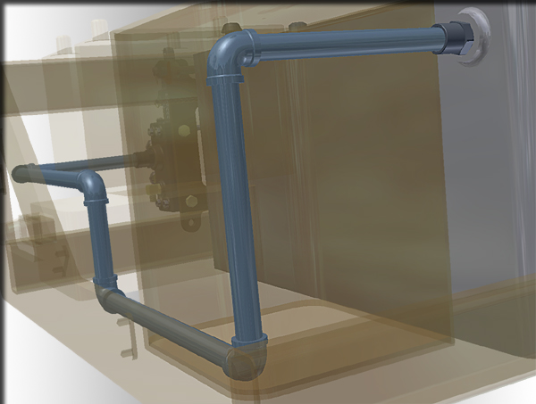
A rigid route can be a series of auto route regions and sketched route segments. Auto route regions are created where geometric constraints are not important or dynamic updates are preferred. Sketched route segments are created to constrain the route to existing geometry or dimensions in a strict manner. Auto route regions can be converted to sketched route segments as you need.
Before or after a route is populated, you can place library fittings and conduit parts onto the route using AutoDrop or place a fitting from within your project work space. Placed fittings help branch off the route or meet appropriate design needs.
What do route sketch colors represent?
 When a rigid route segment or auto route region is defined, the route sketch may present different colors on appropriate route points and segments. By default, they are:
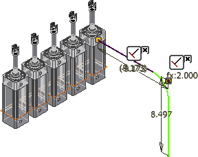
- Purple: The route geometry is fully constrained so all degrees of freedom are removed. Neither translational freedom nor rotational freedom is allowed on the route geometry. Typically, auto route regions and the initial route segment that derives from the selected circular geometry are fully constrained.
- Green: The route geometry is not fully constrained. However, to continue placing new constraints, you may need to delete the appropriate existing geometric constraints and dimension constraints. Otherwise, the route geometry may fail to solve the new constraint and other edits you make.
 Options panel
Application Options Colors tab.
Options panel
Application Options Colors tab.
How do auto route regions and sketched route segments work together to form a rigid route?
You can define your routes as close to the needed results as possible and then adjust later, or you can develop them using precise distances, angles, and constraints as you go.
It is best to plan well for auto route regions and sketched route segments before starting the design. To speed up the creation and plan for dynamic updates, allow the system to automatically create route points whenever possible. Define route points manually where it is critical for a route to correlate to reference geometry or strict dimensions.
How are fittings or gaps added?
In routes of the rigid pipe with fittings type, default fitting are automatically added between all route points. The system determines the fitting to use based on the underlying tube and pipe style. For example, if you have set fitting types of both 90-degree and 45-degree, the system may use a combination of 45-degree and 90-degree elbows to satisfy the route.
Couplings that are associated to model geometry can be turned off while in edit mode by clearing the Fittings check box on the context menu. When the Fittings check box is clear, the fitting does not appear, and the route point remains associated with the object in the assembly.
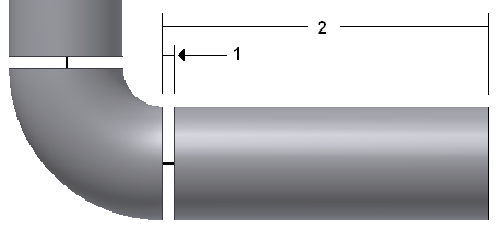
If a butt weld style is selected and gaps are set to display, gaps are automatically added between pipe segments and pipe segments and fittings. Gap display is set in the style. For gaps between a pipe and a fitting within a route, the gap distance (1) is subtracted from the end of the pipe segment (2). The same behavior is true between pipe segments and fittings used to start and end a route.
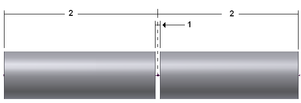
For gaps between pipe segments, the gap (1) is centered on the node and half the gap distance is subtracted from the end of each pipe (2).
Library fittings can be placed on to both populated and unpopulated routes, or anywhere in the background of a tube and pipe assembly. Library conduit parts can be placed anywhere in the background of the graphics window. Non-library fittings in your project work space can also be added. Placed fittings can be connected to an appropriate base fitting or used to create a fork or branch in primary run from which you can start another route. Fittings can also be inserted between two connected fittings or a fitting and a pipe segment.
How do custom bends in rigid piping routes differ from tubing bends?
Though both bends have a bend radius and aim to change the orientation of the route, they differ in the creation workflow:
- Custom bends in rigid piping routes are not defined by style criteria but are always manually created in rigid piping routes. They do not automatically update to dynamic edits.
- Tubing bends are limited to the minimum bend radius defined by style criteria. They can exist between auto route segments and sketched route segments. Tubing bends in an auto route region can dynamically update to assembly edits while tubing bends between sketched route segments are constrained by a fixed radial dimension.
How do auto route regions and sketched route segments differ in responding to assembly changes?
Segments in an auto route region can always dynamically update when changes are made on to associated geometry. The system automatically calculates the new auto route region solution so segments can be added or removed.
Sketched route segments must be manually edited or deleted. The system dynamically adjusts segment length and orientation unless they are fully constrained, but no segments are added or removed.
What violations make error conditions in a rigid route?
Populated routes and runs use the library fittings and conduit parts in the Content Center so you must configure the Content Center correctly. Otherwise, you may fail to retrieve the library data to update the populated routes. In addition, if geometric constraints or dimensions make the route sketch over-constrained, you cannot continue before fixing the route sketch.
Once the system resolves the route edits, violations may still occur. The Model browser hence represents an error icon
![]() beside the route. With the run or route active, you can right-click the route and use Show Violations to identify a list of error conditions. For instance:
beside the route. With the run or route active, you can right-click the route and use Show Violations to identify a list of error conditions. For instance:
- The route does not conform to the style criteria such as the minimum segment length, maximum segment length, and minimum bend radius.
- The route involves invalid angles. For instance, if the rigid piping route involves 45-degree elbows, but it is not included in the style criteria, violations are flagged. If the rigid piping route is self draining and there is a mismatch between the custom elbow and the angle of the run, violations are flagged. If the bent tubing route involves 45-degree and 90-degree directional turns but they are not bound to a tubing bend, say the default tubing bends are manually deleted, violations are flagged.
- The route involves branches.
- The route involves loops.
- The route cannot perform the rigid transformation in positional representation.
- The route is not perpendicular to the circular edge that you select to define the terminal route point.
- The gender or end treatment on the conduit part and fitting do not match. For instance, when defining a rigid piping style, on the Tube & Pipe Styles dialog box, General tab, you have selected a pipe standard with the welded end treatment, as well as a 90-degree elbow standard with the threaded end treatment. Violations hence occur when a route is using this style.
Tip: However, you can use the Connect Fittings command to accomplish the connection between two different end treatments.
- The bend radius in a rigid piping route is smaller than the nominal size of the pipe part. In this case, the segment is consumed by the bend so there is no straight part in the segment.
- The pipe segment to connect two fittings cannot satisfy the minimum or maximum engagement on either end, no matter whether the segment length decreases or increases at the specified increment. The segment increment is defined in the Tube & Pipe Styles dialog box, Rules tab.
- The system dynamically resolves two sketched route points to overlap. It may occur when the included segment in the parametric region is not dimensioned.