
Display
Controls how the shape is displayed in Viewport 2.0.
- Display Bounding Box
- Displays the shape's bounding box.
- Particles
- Displays the shape's particles. Use the Particle Display attributes to further control how the particles are displayed. Note that particles might not be visible if voxels are also being displayed.
- Voxels
- Displays the isosurface of the shape's voxels. Make sure that the viewport is set to one of the shaded modes. Use the Voxel Display attributes to further control the display.
- Voxel Type
-
Controls how voxels are rendered in the viewport.
- Volumetric renders the accumulation of the smoke channel through the volume with a transparency gradient. Use this for aero simulations.
- Levelset renders the surface of the fluid opaquely. Use this for liquid simulations.
Particle Display
Controls the display when Particles is checked in the Display attributes.
- Type
- Displays particles as Point sprites or Sphere instances.
- Max Particle Display Count
- Allows you to display fewer particles in the viewport than are actually simulated, to speed up drawing and free up graphics memory while still displaying a useful preview of the overall particle flow.
Note that for very low values, the number of particles displayed may exceed the value of Max Particle Display Count because the particles get distributed as evenly as possible across the voxels.
In addition, particles are drawn in batches, so it's possible to display more particles than can fit in graphics memory at one time. However, drawing and interactivity will be slower.
Note: If this value is small compared to the total number of particles, you may notice artifacts in the viewport, such as repetitive particle distribution. However, rendering is not affected. - Point Size
- The size of Point sprites in pixels.
- Sphere Radius
- The radius of Sphere instances in scene units.
- Render Particle Size (foam shape only)
-
Controls the size of rendered foam particles.
- Min Level, Max Level
- Restricts the display to particles stored in voxels between the specified tile depths. This can be useful for spatially adaptive simulations. In non-adaptive simulations, particles are always stored at level 7.
- Color
- Displays the selected Color Channel as a color ramp. This can be useful for previewing or diagnosing your simulation. Use the Color Channel Remap attributes to control how the color appears.
Color Channel Remap
- Color Channel Min, Color Channel Max
- Use these attributes to choose the range of values to map to colors. Values outside this range get clipped to the corresponding end of the color ramp.
- Color Ramp
- Use the color ramp to define a gradient from Color Channel Min to Color Channel Max. Vector attributes use the magnitude to drive the color ramp.
- Value Ramp
- Use the value ramp to modify the color channel values before applying the color ramp. This provides finer control over the display, for example, you can clamp and bias values to focus on a specific range.
- Opacity
-
Uses the selected Opacity Channel to control opacity in the viewport. Use the Opacity Channel Remap attributes to control how the color appears. They work in the same way as the Color Channel Remap attributes.
- Numeric
- Displays the numeric values of the selected
Numeric Channel in the viewport.
Tip: Reduce Max Particle Display Count to get a readable sampling of the displayed values.
- Vector
- Displays the selected Vector Channel as vectors in the viewport.
Voxel Display
Controls the display when Voxel is checked in the Display attributes.
- Filter
-
Controls the interpolation used to render voxels in the viewport. Tricubic gives smoother results than Trilinear, especially for aero simulations.
- Quality
- Controls the relative number of samples for drawing voxels in the viewport.
- Diagnostic Color
-
Toggles the display of channel colors for diagnostic purposes.
- When this option is on, you can select a Color Channel and use the Color Channel Remap options to adjust the color ramp. They work in the same way as the Color Channel Remap attributes for particle display.
- When this option is off, the viewports show a preview of the fluid's surface level-set with lighting.
Clipping
Clip Input Mesh lets you preview a slice of the bifrostShape using a mesh object as the clipping boundaries. This is useful for visualizing what is happening in the interior of the simulation for diagnostic or other purposes.
Tile View
Displays the range of voxel resolutions in your simulation as a color-mapped tile tree. This is useful for visualizing what is happening in the interior regions of the simulation for diagnostic purposes, especially when Adaptivity is on.
See Preview Bifröst vowel resolutions using Tile View.
Display
- Enable
- Toggles the tile tree display on and off.
- Min Level, Max Level
- Use these controls to set the range of resolution levels you want displayed. There are eight display levels starting from very coarse (level 0) to fine (level 7). These levels correspond to the range of voxel resolutions in your simulation.
- Focus Level
- Lets you focus the display on a specific level between the set Min Level and Max Level range.
- Focus Falloff
- Sets the width of the focus by controlling the transparency between each level displayed. Increasing this value makes it easier to see all display levels superimposed. A value of 0 displays only the level set by Focus Level. A value of 1.0 displays all of the tiles that are defined by Min Level and Max Level.
Clipping
- Clip Input Mesh
-
Lets you use a polygon mesh to set clipping boundaries of the tile view. This lets you isolate a slice of simulation for investigation.
Color
Use the color ramp to set the start and end colors for the visible tile levels. Color is driven by voxel resolution. The ramp's left most marker sets color for Min Level and right most marker sets color for Max Level.
Render Stats
See Render Stats.
Render
The settings in the Render group control various attributes of the Bifröst shape that are available to be used by renderers such as Arnold. Note that they might not be supported if you are using a different renderer.
- Render As
- Select how to render the shape. In general, use:
- Surface for liquids.
- Points for foam.
- Volume for aero. This is not supported for foam. However, you can still render foam with a volume shader using Points or Surface.
- Velocity Scale
- Multiplier for velocity. This affects motion blur.
- Space Scale
- Uniform scaling factor for the shape. This can be used as an alternative to scaling the shape in the scene.
- Export Channels
- List of channels to export. You must export channels if you want to connect the values as user data in shading networks. Use spaces to separate multiple channel names. Some channels that might be useful to export include:
- age (liquid only — must be enabled in the liquid property's Optional Channels)
- churn (liquid only — must be enabled in the liquid property's Optional Channels)
- density
- ocean (required for ocean blending)
- position
- smoke (aero only)
- temperature (aero only)
- uv (requires a UV projection set in the emitters' properties — not available for foam)
- velocity
Note: You do not need to explicitly export the velocity channel for motion blur. You need to export it only if you want to connect it in a shading network.
- vorticity (liquid only)
Clipping
Renders only the portions of the shape inside the world-space bounding box of a polygon mesh. To specify a mesh, see Work with Bifröst Kill Volume and Clipping input meshes.
Surface Controls
These attributes apply when Render As is set to Surface.
- Render Component
-
- The Voxels option renders the fluid surface as the level set of the signed distance field stored on the voxels. This is not supported for foam.
- The Particles option creates a new signed distance field from the fluid particles, and enables the controls below. This option is similar to using the shape's Meshing Controls, but it does not create a mesh in the scene.
- Droplet Reveal Factor
- Creates and preserves detail around splashes when generating and smoothing the mesh. Lower values result in smoother meshes, while higher values give more small, high-frequency detail.
- Surface Radius
- The radius of each particle blob used to create the surface, in multiples of the Master Voxel Size.
- Droplet Radius
- The radius of each droplet, relative to the Master Voxel Size.
- Kernel Factor
- Controls the width of the surface smoothing kernel. Smaller values give sharper features and higher curvature in the resulting mesh. Larger values result in smoother features.
- Smoothing
- The number of smoothing steps performed on the mesh.
- Resolution Factor
- A scaling factor for adjusting the particle resolution before the mesh is generated. Higher values create more high-frequency detail, but take longer to calculate.
- Hole Kill Threshold
-
Increase this value to eliminate meshed holes in the interior of the fluid. Such holes can occur especially when using high Resolution Factor values with spatially adaptive simulations.
Processing
Controls how the surface is processed. First the surface is dilated, then it is smoothed, and finally it is eroded.
- Dilate
- Value to subtract from the signed distance field before smoothing. This expands the surface to avoid shrinking when smoothing, and helps to preserve small features.
- Smooth
- The amount of smoothing applied in each iteration. Normally, values should be between 0 and 1. Values above 1 can result in distortions.
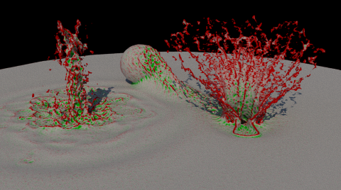
- Smooth Mode
-
Select the type of smoothing to perform. The results are similar but not identical. The choice is a matter of preference. In the images, red areas will be smoothed inwards and green areas will be smoothed outwards.
- LaplacianFlow adds the specified amount of the signed distance field's Laplacian each iteration.
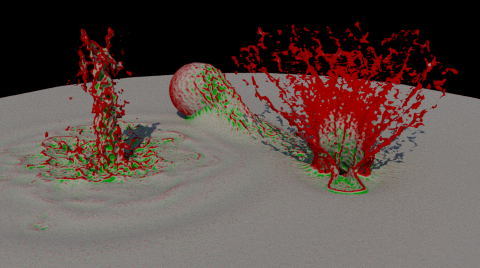
- CurvatureFlow adds the specified amount of the mean curvature each iteration.
- LaplacianFlow adds the specified amount of the signed distance field's Laplacian each iteration.
- Smooth Iterations
- The number of times to repeat the smoothing operation. You can sometimes get better results from repeatedly smoothing by a small amount than from smoothing once by a large amount.
- Erode
- Value to add to the signed distance field after smoothing. This shrinks the surface and prevents it from looking "blobby".
Ocean Blending
These attributes perform a simple blend of the fluid surface with a planar mesh. They can be used for oceans, for example, if you are using a Bifröst simulation for waves and splashes in a specific region, and a mesh for the rest of the ocean surface.
For best results, use a flat planar mesh and a displacement shader such as a vector displacement map generated by BOSS. A deformed mesh can give acceptable results as well, as long as the displacement is not too large (in other words, calm water rather than rough seas). In either case, depressions in the simulated surface might get filled if liquid can flow in from the surrounding ocean.
- Enable
- Enables ocean blending.
- Mesh Plane
- The mesh to blend with the Bifröst shape.
- Boundary Radius
- The radius of the blending region around the intersection of the simulation and mesh surfaces.
- Offsets
- The Y offset can be used to raise or lower the mesh plane to provide a better blend. The X and Z offsets can be used to adjust the plane's horizontal extent: use positive values to expand it or negative values to shrink it.
- Output Channel
- The name of a custom channel to use as a mask when displacing the blended mesh. If you are blending with a flat mesh using displacement, make sure to add this channel to the Export Channels list and then use the channel to control the amount of displacement.
To specify a mesh plane for ocean blending:
- Select Enable.
- Do one of the following:
- In the Attribute Editor menu, select List, and then turn off Auto Load Selected Attributes. This turns off Maya's default behavior of loading attributes for selected objects. The current attributes will now remain loaded in the Attribute Editor when you select the planar mesh.
- Select Copy Tab at the bottom of the Attribute Editor to create a copy of the Bifröst object's attributes in a floating window.
- Select the mesh to use as the ocean surface.
- Click Use Selected.
- Hide the mesh to prevent it from rendering. You should render only the blended surface,
To blend with a flat mesh using displacement:
- Specify the flat plane for which the displacement map was created as the Mesh Plane.
- Specify the name of the Output Channel to use for blending. The default is ocean.
- Add the same channel name to the Export Channels list.
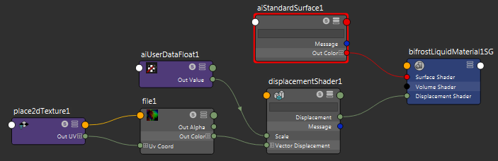
- In the Hypershade window, add a displacement shader to the liquid material. For more information about working in the Hypershade window in general, see Hypershade window.
- Connect a File texture node to the displacement shader's Vector Displacement attribute.
- Specify the displacement map in the File node's Image Name attribute.
- Use a utility shader to get the
Output Channel you specified (for example,
ocean) and connect it to the displacement shader's
Scale attribute. The name of the shader and the procedure for this step depend on your renderer.
- Adjust the Boundary Radius and Offsets to control the blend.
To blend with a deformed mesh:
- Specify the deformed plane as the Mesh Plane.
- Adjust the Boundary Radius and Offsets to control the blend.
Advanced
- Export Laplacian
- Exports the Laplacian of the signed distance field. This makes the laplacian channel available to be used as user data in a shading network.
- Export Curvature
- Exports the mean curvature of the level set. This makes the curvature channel available to be used as user data in a shading network.
Point Controls
These attributes apply when Render As is set to Points.
- Radius
- The radius of the points in scene units.
- Modulate Radius With Channel
- Multiples the Radius by the specified Radius Channel. For example, if Radius Channel is set to density, then points are larger where density is high and smaller where density is low.
Volume Controls
These attributes apply when Render As is set to Volume.
- Smooth
- The amount of smoothing applied in each iteration.
- Smooth Iterations
- The number of smoothing iterations.
Bifrost Meshing
- Enable
- Generates a polygon mesh for the bifrostMesh object.
- Droplet Reveal Factor
- Creates and preserves detail around splashes when generating and smoothing the mesh. Lower values result in smoother meshes, while higher values give more small, high-frequency detail.
- Surface Radius
- The radius of each particle blob used to create the surface, in multiples of the Master Voxel Size.
- Droplet Radius
- The radius of each droplet, relative to the Master Voxel Size.
- Kernel Factor
- Controls the width of the surface smoothing kernel. Smaller values give sharper features and higher curvature in the resulting mesh. Larger values result in smoother features.
- Smoothing
- The number of smoothing steps performed on the mesh.
- Resolution Factor
- A scaling factor for adjusting the particle resolution before the mesh is generated. Higher values create more high-frequency detail, but take longer to calculate.
- Hole Kill Threshold
-
Increase this value to eliminate meshed holes in the interior of the fluid. Such holes can occur especially when using high Resolution Factor values with spatially adaptive simulations.
- Flip Face Normals
- Reverses the order of the vertex indices in the triangles of the final mesh so that normals are flipped.
Clipping
Clip Input Mesh lets you preview a slice of the Bifröst output mesh using a polygon object as the clipping boundaries. This is useful for visualizing what is happening in the interior of the simulation for diagnostic or other purposes.
Channel Transfer
- Velocity Scale
- A set of XYZ scaling factors used when transferring the velocity channel from the voxels to the vertex color map on the mesh.