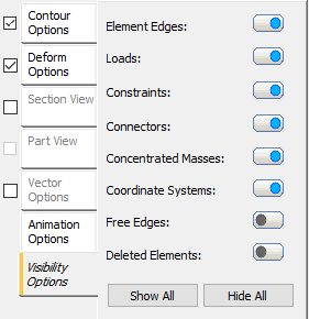
Right-click on Displacement in a subcase and select Edit. Click on the Visibility Options tab and the form looks as shown in the figure below.

These options allow you to switch the symbols or highlighting on and off using the flip button:
- Element Edges: This option, when set to ON (blue), displays the element edges. It is equivalent to the Mesh option in the Object Visibility settings (accessed from the Display panel of the ribbon).
- Loads: This option, when set to ON (blue), displays the loads.
- Constraints: This option, when set to ON (blue), displays the constraints.
- Connectors: This option, when set to ON (blue), displays the connectors.
- Concentrated Masses: This option, when set to ON (blue), displays the concentrated masses.
- Coordinate Systems: This option, when set to ON (blue), displays the coordinate systems.
- Free Edges: This option, when set to ON (blue), displays the free edges for shell elements. The program overlays the free edges with a heavy white line. Free edges are those that are not mated with an adjacent shell element edge. This option is useful for finding improperly connected shell elements where faces intersect each other.
 You can also control visibility of these items by clicking
Display
 Object Visibility in the
Autodesk Inventor Nastran ribbon tab and activating/deactivating the individual items from there. See the
Object Visibility page for more information.