Creep Characteristics
Description: Defines creep characteristics based on experimental data or known empirical creep law.
Format:

Example:

| Field | Definition | Type | Default |
|---|---|---|---|
| MID | Identification number of a MAT1, MAT2, MAT9, or MAT12 entry. | Integer > 0 | Required |
| T0 | Reference temperature at which creep characteristics are defined. See Remark 2. | Real or blank | 0.0 |
| EXP | Temperature-dependent term,
 , in the creep rate expression. See Remark 2. , in the creep rate expression. See Remark 2.
|
Real or blank | 1.0E-9 |
| FORM | Form of the input data defining creep characteristics, one of the following character variables: CRLAW for empirical creep law or TABLE for tabular input data of creep model parameters. | Character | Required |
| TIDKP, TIDCP, TIDCS | Identification number of a
TABLES1 entry, which defines the creep model parameters
 , ,
 , and , and
 , respectively. See Remarks 3 through 5. , respectively. See Remarks 3 through 5.
|
Integer > 0 | Required |
| THRESH | Threshold limit for creep process. Threshold stress under which creep does not occur is computed as THRESH multiplied by Young's modulus. | Real or blank | 1.0E-5 |
| TYPE | Identification number of the empirical creep law type, one of the following integers: 111, 112, 121, 122, 211, 212, 221, 222, or 300. Not required if FORM = TABLE. See Remarks 1 and 3. | Integer > 0 | |
| a - g | Coefficients of the empirical creep law specified in TYPE. Not required if FORM = TABLE. See Remark 1. | Real or blank |
Remarks:
- This entry will be activated if a MAT1, MAT2, MAT9, or MAT12 entry with the same MID is used and the NLPARM entry is prepared for creep analysis.
- The creep formulation is principally suited for isotropic materials and when used with anisotropic materials may produce incorrect results. However, slightly anisotropic materials may produce acceptable results.
- Two classes of empirical creep law are available.
- Creep Law Class 1 - The first creep law class is expressed as:

Parameters
 ,
,
 , and
, and
 are specified in the following form, as recommended by Oak Ridge National Laboratory:
Parameters Function 1 Digit Function 2 Digit 

i = 1 
i = 2 

j = 1 
j = 2 

k = 1 
k = 2 TYPE = ijk where i, j, and k are digits equal to 1 or 2, according to the desired function in the table above. For example, TYPE=122 defines
 ,
,
 , and
, and
 .
.
- Creep Law Class 2 - The second creep law class is expressed as:
 where the values of b and d must be defined as follows:
- 1.0 < b < 8.0
- 0.2 < d < 1.0
The coefficient g should be blank if TYPE = 112, 122, 222, or 212 and c, e, f, and g should be blank if TYPE = 300. The coefficients a through g are dependent on the structural units; caution must be exercised to make these units consistent with the rest of the input data.
- Creep Law Class 1 - The first creep law class is expressed as:
- Creep law coefficients a through g are usually determined by least squares fit of experimental data, obtained under a constant temperature. This reference temperature at which creep behavior is characterized must be specified in the T0 field if the temperature of the structure is different from this reference temperature. The conversion of the temperature input (°F or °C) to °K (degrees Kelvin) must be specified in the PARAM,
TABS entry as follows:
- PARAM, TABS, 273.16 (If Celsius is used.)
- PARAM, TABS, 459.69 (If Fahrenheit is used.)
When the correction for the temperature effect is required, the temperature distribution must be defined in the Bulk Data entries (TEMP, TEMPP1 and/or TEMPRB), which are selected by the Case Control command TEMP(LOAD) = SID, TEMP(MATERIAL) = SID, or TEMP(BOTH) = SID within the subcase.
- From the thermodynamic consideration, the creep rate is expressed as:

where,
 = strain/second per activation
 = energy of activation
R = gas constant (1.98 cal/mole °K)
T = absolute temperature (°K)
- If the creep characteristics are defined at temperature T0, the creep rate at temperature T is corrected by a factor:

where,
 = corrected creep rate
 = creep rate at T0
 = correction factor
Note that EXP refers the field EXP and not the mathematical function for ex.
- Creep model parameters
 ,
,
 , and
, and
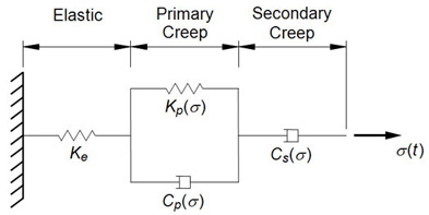
 represent parameters of the uniaxial rheological model as shown in the following figure.
Tabular values (Xi, Yi) in the TABLES1 entry correspond to
 ,
,
 , and
, and
 for the input of
 ,
,
 , and
, and
 , respectively. For linear viscoelastic materials, parameters
 ,
,
 , and
, and
 are constant and two values of
 must be specified for the same value of
 ,
,
 , and
, and
 .
.

Figure 1. CREEP Parameter Idealization
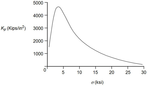
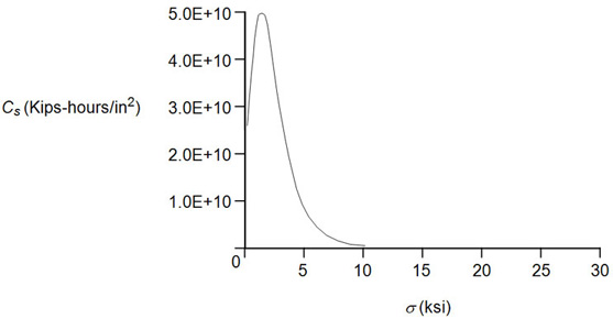
Creep model parameters, as shown in the figures below, must have positive values. If the table look-up results in a negative value, the value will be reset to zero and a warning message will be issued.

Figure 2. K p Versus σ Example for CREEP

Figure 3. C p Versus σ Example for CREEP

Figure 4. C s Versus σ Example for CREEP