Assembles and manages drawings belonging to a project.
 Ribbon: Home tab
 Project panel Project Manager
  Command entry:
projectmanager
Command entry:
projectmanager 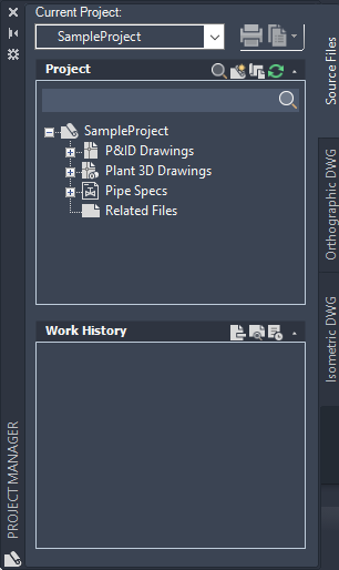
Project Controls
Provides a way to open projects and run project reports.
- Project Name
-
Displays the name of the current project. By default, the last project you opened is displayed.
The first time you open the Project Manager, a default project is displayed. The Project Name list also displays the following options:
- Previously Opened Projects. Displays a list of the most recently opened projects.
- Open. Displays the Open dialog box, where you can find and select an existing project.xml file.
- New Project. Displays the Project Setup Wizard.
- Sample Project. Displays the sample project provided with the product.
- Publish button

-
Displays the Publish dialog box.
- Reports button

-
Displays a list of reports that you can run, including custom reports.
- Data Manager. Displays the Data Manager.
- Export Data. Displays the Export Report Data dialog box.
- Import Data. Opens the Import From dialog box.
- Reports. Opens the Data Manager in Project Reports mode.
Project Panel
Sets the overall organization for the drawings in the project.
You can add, remove, and reorder drawings and folders. You can also select drawings or folders to include their data in reports.
- Project Panel Toolbar
-
Provides buttons that open, add, and refresh the status of drawings.
 Hide/Show search box. Hides or displays the search box, where you can search the project for specific filenames.
-
 New Drawing. Displays the New DWG dialog box, where you can create a new drawing based on the default template and add it to the project tree.
-
 Copy Drawing to Project. Opens the Select Drawings to Copy to Project dialog box, where you can select one or more files to copy to the project.
-
 Refresh DWG Status. Verifies whether any of the drawings or files in the project are being edited by another user.
Note: Refresh can also synchronize the drawing with the project. Automatic synchronization is set with synchstylesmode. - Project Tree Nodes
-
Each node in the project tree is designated by a specific icon.
-
 Project Node. Represents the top-level organizational unit in the project tree hierarchy.
Note: The icon next to the Project Node indicates which type of project it is. For example, a collaboration project has the BIM 360 icon
Project Node. Represents the top-level organizational unit in the project tree hierarchy.
Note: The icon next to the Project Node indicates which type of project it is. For example, a collaboration project has the BIM 360 icon next to it.
-
 P&ID Drawings Node. Represents a default grouping for P&ID drawings that cannot be removed. You can add nested folders within this folder.
-
 Plant 3D Drawings Node. Represents a default grouping for Plant 3D drawings that cannot be removed. You can add nested folders within this folder.
-
 Related Files Node. Represents a default grouping for Related Files that cannot be removed. Also represents folders that you can create under any default grouping.
-
 Drawing Node. Represents a drawing in the project.
Note: In a collaboration project, there is a circle next to each drawing node that represents whether you have a drawing checked out or not. The circle only displays if the file has been locally cached which happens when it is opened.
Drawing Node. Represents a drawing in the project.
Note: In a collaboration project, there is a circle next to each drawing node that represents whether you have a drawing checked out or not. The circle only displays if the file has been locally cached which happens when it is opened. Not Checked Out
 Checked Out
-
 Locked Drawing Node. Represents a drawing that is currently being edited.
-
 Missing Drawing Node. Represents a drawing that has been moved or removed.
-
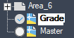
 Referenced Drawing (Xref) Node. Represents a drawing that is referenced by the project.
-
Details Panel
Provides information about the project or about drawings selected in the Project Manager tree area.
To change the display, click the corresponding button on the Details panel toolbar.
- Details

-
Displays information about the selected node.
- Project details. Displays project information, including project location, name, description, unit type, and number.
- Drawing details. Displays the drawing status, description, file name, location, file size, and the save and edit dates.
- Preview

-
When a drawing node is selected, displays a small preview of the drawing.Note: In collaboration projects, you are able to see a preview of the drawing before opening the drawing.
- Work History (Source Files tab only)

-
When a drawing is selected, displays all work history entries for the drawing.
Times and dates use the current Windows system settings.
- Date Modified. Displays the date and time of the edits associated with the most recent work history entry.
- User. Displays the login name of the person who opened the drawing for editing.
-
Status. Displays the status of the drawing. Status categories differ, depending on the standards used by your business. They may include the following:
- Unassigned. No status is assigned.
- In Progress. Project is open for editing.
- For Review. Project is ready for review.
- Revision 1-4. Draft number of the project.
- Final. Project is final.
- Archive. Project is ready to be archived.
- Manage. Displays the Project Status Manager, where you can customize the status options.
- Notes. Displays descriptions entered by the individual updating the work history. Only the originator of the work history record can update existing notes.
Shortcut Menus: Project Tree Nodes on All Tabs
The following options, listed in alphabetical order, are displayed when you right-click a node on the project tree. The options available depend on the type of node you select.
| Menu Option | Tab | Node | Description |
|---|---|---|---|
| Add Work History |
|
|
Displays the Work History dialog box, where you can update status and add notations. |
| Audit Project |
|
|
Checks the project for errors. |
| Check In |
|
|
Checks in the checked out asset. |
| Check Out |
|
|
Checks out the selected asset(s). |
| Cleanup Cached Files |
|
|
Removes locally cached drawing files. |
| Close Project |
|
|
Closes the current project. |
| Collapse |
|
Added folder | Collapses the contents of the folder and places a plus sign in front of the folder name. |
| Copy Drawing to Project |
|
|
Displays the Select Drawings to Copy to Project dialog box. |
| Copy File to Project |
|
|
Displays the Select Files to Copy to Project dialog box. Files are copied to the project folder. AutoCAD drawings can be selected but cannot contain plant objects. |
| Create Adjacent View |
|
|
Creates a new view adjacent to the current one, for example, top or bottom. |
| Data Manager |
|
|
Displays the Data Manager. |
| Delete View |
|
|
Deletes the orthographic view. |
| Drawing Autogen Properties |
|
|
Displays the Drawing Autogen Properties dialog box, where you can set automatically generated properties for drawings. |
| Edit View |
|
|
Displays the OrthoCube in the Orthographic View Selection window. You can edit the ortho view configuration, choose models to include, change the scale, and so on. |
| Export Data |
|
|
Displays the Export Report Data dialog box. |
| Export to PCF |
|
|
Displays the Save PCF As dialog box. |
| Filter For |
|
|
Displays a box where you can enter filtering criteria to view only desired line numbers. |
| Import Data |
|
|
Displays the Import From dialog box. |
| Link to File |
|
|
Displays the Select Files to Link to Project dialog box. Files are not copied to the project folder. |
| Locate Drawing |
|
|
Locates a drawing you have renamed or moved. You can use this option to find a drawing that is displayed in the Project Manager with a missing-file icon. |
| Lock Line and Issue |
|
|
Lock lines to indicate that they have been sent for fabrication and should no longer be changed. |
| New Drawing |
|
|
Displays the New DWG dialog box. |
| New Folder |
|
|
Displays the Project Folder Properties dialog box, where you can create a new folder. |
| Open |
|
|
Displays the selected drawing. |
| Open Read-only |
|
|
Displays the selected drawing with a read-only status. You cannot save changes to drawings opened as “read-only.” |
| Options |
|
|
Displays the Collaboration Options dialog box. |
| Production ISO |
|
|
Displays the Create Production Iso dialog box, where you can create a new isometric drawing. |
| Properties |
|
|
Sets information about the selected node. If a project is selected, the dialog box is displayed. If a folder is selected, the Project Folder Properties dialog box is displayed. If a drawing is selected, the Drawing Properties dialog box is displayed. |
| Publish |
|
|
Specifies drawing sheets that you can assemble, reorder, rename, copy, and save for publishing as a multi-sheet drawing set. |
| Quick ISO |
|
|
Displays the Create Quick Iso dialog box, where you can create a new isometric drawing. |
| Refresh from Project |
|
|
Updates your local project files and settings from the cloud collaboration project. |
| Refresh Xref List |
|
|
Refreshes and updates the list of xrefs for a drawing. |
| Remove Drawing |
|
|
Deletes the selected drawing from the project. This action does not remove the drawing from your computer. |
| Remove File |
|
|
Deletes the selected file from the project. This action does not remove the file from your computer. |
| Remove Folder |
|
|
Deletes the selected folder from the tree. This option is available only for folders that do not have nested folders or drawings. |
| Rename Drawing |
|
|
Renames project drawings. Not available for nested xrefs and read-only files. |
| Resave All Project Drawings |
|
|
Saves edits made to all open project drawings or all drawings that have been modified during the current session. |
| Show Xrefs in Use |
|
|
Checks unopened drawings for xrefs and lists the xrefs in the Project Manager. |
| Undo Check Out |
|
|
Undoes the check out of the selected asset(s) without including any changes. |
| Unlock Line |
|
|
Unlocks lines that have previously been locked. |
| Update Annotation |
|
|
Updates annotations in the ortho drawing to reflect changes in the referenced model. |
| Update View |
|
|
Updates a view in the ortho drawing to reflect changes in the referenced model. |
| Update Views |
|
|
Updates all views in an ortho drawing to reflect changes in the referenced model. This operation can take time, depending on the complexity of the model and the number of views. |
| Validate |
|
|
Runs the validation program for one or more P&ID drawings and displays a list of errors in the Validation Summary window. |
| Validate Project |
|
|
Runs the validation program for the entire project and displays a list of errors in the Validation Summary window. |
| Validate View |
|
|
Validates a view in the ortho drawing against the referenced model to see if changes have been made. If so, the view or drawing can be updated. |
| Validate Views |
|
|
Validates all views in the ortho drawing against the referenced model to see if changes have been made. If so, the drawing can be updated. |
| Validation Settings |
|
|
Displays the P&ID Validation Settings dialog box, where you can control the type of validation errors that are flagged. |
| Validation Summary |
|
|
Displays the Validation Summary window, where you can view a summary of flagged errors. |
| Xref into current drawing |
|
|
Xrefs the selected drawing in the current drawing |