You can change graphical properties such as layers, colors, linetypes, and lineweights.
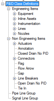
- In the Project Setup tree view, expand P&ID Class Definitions.
- Continue to expand the list until you locate and click the component or line whose linetype you want to change.
- On the Class Settings pane, do one of the following:
- If you are modifying a component, under Symbol, in the drop-down list, click the symbol you want to modify. Click Edit Symbol.
- If you are modifying a line, under Line, click Edit Line.
- In the Settings dialog box, under General Style Properties, locate and click the property you want (for example, linetype, lineweight, layers, and colors) In the corresponding drop-down list, click the property you want.
Note: If your project is based on the DIN 2481 standard, and the pipe line you want to change has multiple lines, change Sline Type to Mline. Then click Mline style. In the drop-down list, click a new multiline style. The DIN standard uses multiple lines to represent oil, air, solid fuels, and so on.
- Click OK.
When designers place the component in a drawing or create a schematic line, it is displayed with the properties you defined here.