Open the Coordinate System Transformation dialog by clicking Edit menu > Edit > Coord. system transformation.
The option is used for transformation (combination of translation, rotation and scaling, if need be) of coordinate systems. This lets you define a structure using a familiar and simple coordinate system and translate (copy) it to a different place. For example, a structure that is part of a curved bridge or viaduct has the same geometry at the beginning and end (bridge heads or first and last span); however, the position (coordinates of snap points) for the end of the bridge is difficult to determine. You can define the initial structure elements in a convenient coordinate system and using a transformation of this coordinate system, move (copy) these elements to the resultant position.

To transform a coordinate system:
- Determine the Initial coordinate system
The coordinate system can be defined using either method:
- As a complete definition of a coordinate system, consisting of defining the coordinates of the coordinate system origin (P0 point) as well as the directions of the coordinate system axes x, y, and z (coordinates of points: PX, PY, and PZ).
- As a definition of the coordinates of the coordinate system origin (P0 point). The coordinate system axes are compatible with the axes of the global coordinate system.
- Determine the Resultant coordinate system, that is, specify the coordinates of the coordinate system origin (P0 point) as well as the directions of the coordinate system axes x, y, and z (coordinates of points: PX, PY, and PZ).
When the Orthogonal systems without scaling option is selected, the coordinate system axes (x, y, z axes) are perpendicular both in the initial and resultant coordinate system and the coordinate system axes are not scaled. The lengths of segments P0-PX, P0-PY, and P0-PZ are identical in both coordinate systems.
When Orthogonal systems without scaling is cleared:
- Axes of both initial and resultant coordinate systems do not have to be perpendicular to each other.
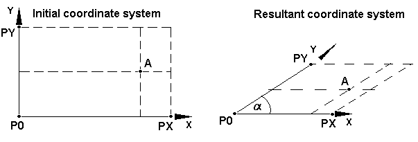
- Axis directions are defined by specifying the position of the points: PX, PY, and PZ for the initial and resultant coordinate systems. The lengths of the segments: P0-PX, P0-PY, and P0-PZ for the initial and resultant coordinate systems do not have to be identical, thus, determining the position of any point in the resultant coordinate system is based on the proportions between the segments defining the individual axes in the initial and resultant coordinate systems. The following example shows such a situation (for a 2D coordinate system): the initial coordinate system is an orthogonal one; whereas, the axes of the resultant coordinate system intersect at the a angle; position of point A is displayed in the initial and resultant coordinate system.

Clicking Parameters opens an additional dialog.
When you click Execute, the transformation is performed.