When you add a masking region to a model family, several parameters allow you to control the visibility of the masking region and where the masking region is drawn.
You can specify the following properties for masking regions in model families:
- If the masking region is visible when the family is loaded into a project and placed in the drawing area.
- The detail levels at which the masking region is visible (coarse, medium, or fine).
- Where the masking region is drawn. This is controlled by the Draw in Foreground parameter. When this parameter is selected, the masking region is drawn at the detail plane of the view (the plane that is closest to you as you look at the view). When this option is not selected, the masking region is drawn on the work plane on which it was sketched.
Controlling Where Masking Regions are Drawn in Model Families
Where a masking region is drawn depends on where it is sketched in the family and the status of the Draw in Foreground parameter. It is also important to consider other families with which the family may interact as you determine where you want the masking region drawn. The following scenarios illustrate sample families and the placement of their masking regions.
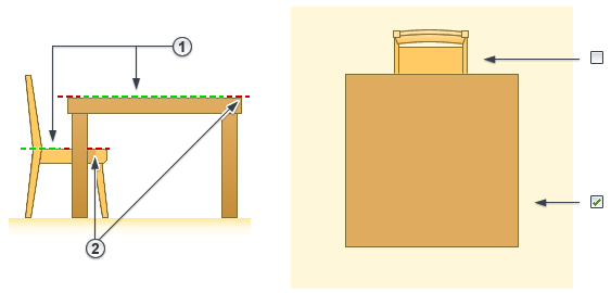
Scenario 1
The following images show a chair family and a table family, both with their masking region (red, dashed line) sketched on the reference level ![]() . In the first image, the Draw in Foreground parameter is selected for both the table and the chair. The chair masks the table, because the chair back is higher than the table
. In the first image, the Draw in Foreground parameter is selected for both the table and the chair. The chair masks the table, because the chair back is higher than the table ![]() .
.

In the second image, the Draw in Foreground parameter is cleared for the chair so that the masking region is drawn where it was sketched. The Draw in Foreground parameter is still selected for the table. Therefore, the table masks the chair. In this image, ![]() indicates the work plane on which the masking regions are drawn, and
indicates the work plane on which the masking regions are drawn, and ![]() indicates the work plan on which the masking regions are sketched.
indicates the work plan on which the masking regions are sketched.

Scenario 2
The following images show the same chair and table families, but the masking regions are sketched on different work planes ![]() . In the first image, the Draw in Foreground parameter is selected for both the table and the chair. Again, the chair masks the table, because the chair back is higher than the table
. In the first image, the Draw in Foreground parameter is selected for both the table and the chair. Again, the chair masks the table, because the chair back is higher than the table ![]() .
.

In the second image, the Draw in Foreground parameter is cleared for the chair and selected for the table. Therefore, the table masks the chair.
Scenario 3
The following image shows a cabinet family and a counter top family. The goal is for both the counter top and the cabinet to display in plan view when the counter top is placed on top of the cabinet. Both families have masking regions (as shown by the red, dashed lines ![]() ). In order to accomplish the goal, clear the Draw in Foreground parameter for the counter top family, and select the Drawn in Foreground parameter for the cabinet family.
). In order to accomplish the goal, clear the Draw in Foreground parameter for the counter top family, and select the Drawn in Foreground parameter for the cabinet family.

Adding a Masking Region to a 2D Element in a Model Family
If you create a model family that only contains 2D elements (for example, a 2D toilet fixture) and you want to apply a masking region to the 2D element, you must include an invisible line to represent the Z dimension, which is where the masking region is drawn. The invisible line must be drawn above the level and must be a minimal length (such as 1/8”) so that the masking region does not obscure any other elements in the view.