If you have existing designs created using other CAD software, you can import or link them into a Revit model to use as a starting point for your design.
In addition to using the Import CAD and Link CAD tools, you can import CAD files using drag-and-drop from Windows® Explorer onto a model, drafting, or sheet view of Revit.
You can mirror imported and linked CAD files. See Mirror Elements.
Import vs. Link
In most cases linking is preferred over importing CAD files. Links are more easily managed from the Manage Links Dialog and can be loaded and unloaded as needed. Linked CAD files will also update when reloaded, if changes of the CAD file are anticipated, link the file. Imported categories are not added to the Revit model when using links. Added categories can affect performance and make it difficult to manage the display of imported CAD files.
Imported CAD files allow for direct changes to the geometry if exploded. Exploded CAD imports can affect model performance, so consider carefully before importing CAD files. See Explode Imported Geometry.
Snapping to Imported Geometry
Suppose that you import an AutoCAD® drawing into Revit and then want to trace over walls in that drawing. As you place the cursor near the lines representing the walls, it can snap to the lines or the midpoint between the lines.
When you import 3D shapes using SAT or 3DM (Rhino) files, you can use the imported shapes as references for dimensioning, snapping, and aligning. See About Importing 3D Shapes.
Proxy Graphics from AutoCAD Files
Revit supports reading in proxy graphics from AutoCAD files. Proxy graphics are AutoCAD's representations of AutoCAD Architecture objects. Unlike AutoCAD Architecture objects, proxy graphics have no intelligence.
Proxy graphics can exist for many types of data in AutoCAD, including Mechanical Desktop (MDT) parts and AutoCAD Runtime eXtension (ARX) objects. If you set the Proxygraphics command to 1 in AutoCAD, Revit can then import ARX objects and AutoCAD Architecture objects (such as walls and floors) in the DWG or DXF file.
Subdivision Surfaces and Solids Created in AutoCAD
Revit can import DWG files containing subdivision surfaces and solids created in AutoCAD. Some complex subdivision meshes may fail to convert to a traditional solid or surface altogether, or generate a problematic solid or surface. Other highly complex SubD meshes may not import completely or at all.
3D Mesh Internal Edges
|
Internal Edge Removal Examples |
|
|---|---|
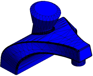 |
Model with internal edges shown. Internal edges will be removed automatically when imported/linked into Revit. |
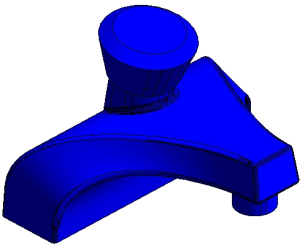 |
Model as it appears in Revit with internal edges removed. |
 |
Model with internal edges removed, but mesh from the source file caused the facets of the mesh to remain. The mesh in this case does not contain enough information for Revit to apply graduated shading in order to smooth the surface. |
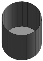 |
Model of open-topped cylinder, the internal triangulation edges are removed but the vertical edges were not removed because they were not identified as internal edges. |
DGN Conversion
|
DGN to Revit Conversion Table |
||
|---|---|---|
|
MicroStation |
Autodesk Product |
Notes |
| Geometric Elements | Geometric Objects | The following DGN elements are translated into an import symbol: line, SmartLine, LineString, multiline, shape, complex chain, complex shape, arc, ellipse, curve, B-spline curve, and pattern. Pattern elements are limited to simple pattern styles. Bitonal gradient properties are also supported. |
| Levels |
Layers |
DGN levels are mapped automatically into an import symbol. Invalid DGN characters in level names are converted to spaces. |
| Colors | Colors | All colors are translated using RGB values when the Preserve option is selected for colors. |
| Line Styles | Linetypes |
For the correct display of linetypes, the MicroStation .rsc (resource file) that is referenced by the DGN file must be available on your computer in a valid Support File search path when you import or attach the DGN file. Dynamically scaled line styles (Standard DGN Line Styles 1-7) are converted into fixed-scale linetypes. The resulting linetypes take into account the current zoom factor in a view in the DGN file when they are imported or attached as a DGN file into Revit. Note:
To import standard V7 line styles correctly, you must “Fit View” and “Save Settings” in MicroStation first. |
| Cells |
Blocks |
Cells are converted into blocks. Tags that are associated with cells are converted into constant-mode block attributes. |
| Text Elements, Text Styles | Single-line Text Objects, Multiline Text Objects, Text Styles | TrueType fonts are imported as text elements. |
| Tables | Tables | Cells that represent tables in DGN are imported as blocks. |
| Dimensions, Dimension Styles | Dimensions, Dimension Styles | The size, spacing, style, and shape of dimensions may vary slightly. Dimension associativity is maintained whenever possible. |
| Fields | Fields |
In general, fields are translated as static text. The exceptions are fields that behave identically in both products. This includes the Date fields CreateDate, SaveDate, and PlotDate, and the Document property fields Author, Filename, and Filesize. Fields are converted to text when “Explode Text Nodes to Text Elements” is checked in the Import DGN Settings dialog box. |
| Raster Images | Raster Images | These image file types: .bmp, .cal, .tif, .png, .tga, .jpg, .pcx, .gif, .rlc, .bil, and .pct are supported. All other image file types are not. |
| DGN References | DWG References | .dwg and .dgn file types are supported. Other non-DGN file types such as .cel, .h, .s, .d, .rdl, and .cgm are also supported. |
| DGN Design Model | DWG Model | The selected design model in a DGN file is converted into a DWG file. |
| DGN Sheet Model | DWG Layout | Only the sheet models that reference the primary design model are imported. DGN sheet models are translated as layouts in a DWG file. |