Modify grid lines, such as line style for the center segment or the symbol used for the ends of the grid line, on the Type Properties dialog.
To change type properties, select an element and click Modify tab Properties panel
![]() (Type Properties). Changes to type properties apply to all instances in the project.
(Type Properties). Changes to type properties apply to all instances in the project.
| Name | Description |
|---|---|
| Graphics | |
| Symbol | The symbol to use for the ends of a grid line. The symbol can display a grid number in a bubble (Grid Head–Circle), a grid number but no bubble (Grid Head–No Bubble), or no grid bubble or number (none).
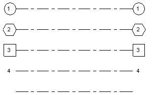 |
| Center Segment | The type of center segment to display in the grid line. Select None, Continuous, or Custom. See
About Customizing Grid Lines.
 |
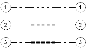
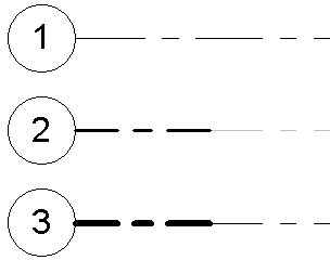
| Center Segment Weight | If the Center Segment parameter is Custom, the line weight is used for the center segment.
 |
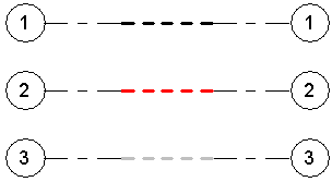
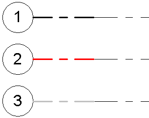
| Center Segment Color | If the Center Segment parameter is Custom, the line color is used for the center segment. Select a color defined in
Revit, or define your own color. See
About Colors.
 |
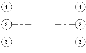
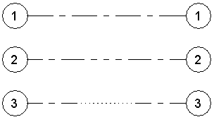
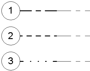
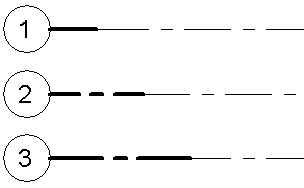
| Center Segment Pattern | If the Center Segment parameter is Custom, the pattern is used for the center segment. The line pattern can be solid or a combination of dashes and dots.
 |
| End Segment Weight | The line weight to use for a continuous grid line, or if Center Segment is None or Custom, the line weight for the end segments.
 |
| End Segment Color | The line color to use for a continuous grid line, or if Center Segment is None or Custom, the line color for the end segments.
 |
| End Segment Pattern | The line style to use for a continuous grid line, or if Center Segment is None or Custom, the line style for the end segments.
 |
| End Segments Length | If the Center Segment parameter is None or Custom, the length of the end segments (in paper space).
 |
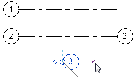
| Plan View Symbols End 1 (Default) | In a plan view, the default setting to display a bubble at the start point of a grid line. (That is, when you draw a grid line, the bubble displays at its start point.) If desired, you can show or hide bubbles for individual grid lines in views. See
Show and Hide Grid Bubbles.
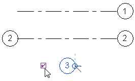 |
| Plan View Symbols End 2 (Default) | In a plan view, the default setting to display a bubble at the endpoint of a grid line. (That is, when you draw a grid line, the bubble displays at its endpoint.) If desired, you can show or hide bubbles for individual grid lines in views. See
Show and Hide Grid Bubbles.
 |
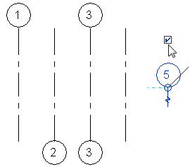
| Non-Plan View Symbols (Default) | In project views other than plan views (such as elevations and sections), the default location where bubbles display on the grid line: Top, Bottom, Both (top and bottom), or None. If desired, you can show or hide bubbles for individual grid lines in views. See
Show and Hide Grid Bubbles.
 |