When structural framing elements join in a model, geometry between the 2 elements adjust in the simplest manner and not necessarily as you intend.
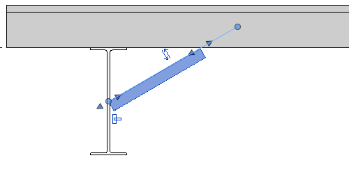
You can manually adjust the geometry of the joined elements but with limited results. In the following example, a purlin is tied to a beam with a light gauge angle brace. The brace joins to the origin of the beam and purlin by default.

The position of the location line is controlled by the joining mechanism. Disjoining allows you to manipulate the location line.
To adjust the end position of the brace closer to the lower flange of the beam, you must first disjoin the brace end position. Right-click the join (blue circle) and select Disallow Join from the context menu. You can disallow the join on either end of the beam if necessary.
Notice the icon in the drawing area showing that the join is now currently disallowed. You can click that icon to rejoin the brace to its original position.
Next, drag and snap the disjoined brace along the beam geometry.

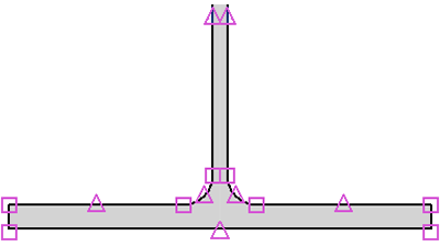
Midpoints and endpoints of the web and flange are also characteristic points to which the brace will snap. The following image highlights some of these points.