Reposition beams and braces in relation to their location lines.
- Select either a beam or brace. The location line of the element becomes active.
- Click Modify | Structural Framing tab
 Justification panel
 (Justification Points).
If the Justification Points tool is unavailable, one of the following may be the issue:
(Justification Points).
If the Justification Points tool is unavailable, one of the following may be the issue:
- The yz Justification instance property is specified as Independent.
- The element is pinned in position, such as members of trusses and beam systems.
- More than one element is selected
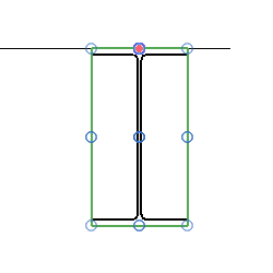
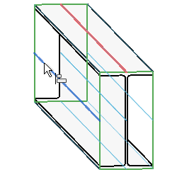
Sixteen colored lines representing the justification options display along the beam. In many cases, only 9 lines representing the justification options are visible along the beam because some of these lines overlap. You can tab select each of the sixteen lines if necessary.
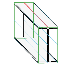
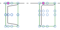
Channel beams and L-beams possess different family origins and geometrical centers that better display the sixteen justification points.
 The colors represent the following:
- Red: The current justification of the framing element.
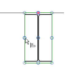
- Blue: Origin justification lines at the top, bottom, left, and right of the framing element.
- Green: Bounding box borders at the top left, top right, bottom left, and bottom right of the framing element.
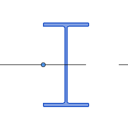
- Click a justification point or line from which the framing element geometry will justify.
The y Justification and z Justification parameters in the Properties palette change to match the new justification of the physical geometry of the framing element. In this example, the values are Origin and Left respectively. Note how the geometry adjusts from the location line.