Outlet Condition
In this step, we assign an ambient pressure condition to the valve outlet. (This is the typical way to model where flow leaves the device.)
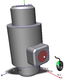
Left click on the outlet surface:
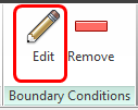
Click Edit from the Boundary Conditions context panel:
On the Type row, select Pressure.
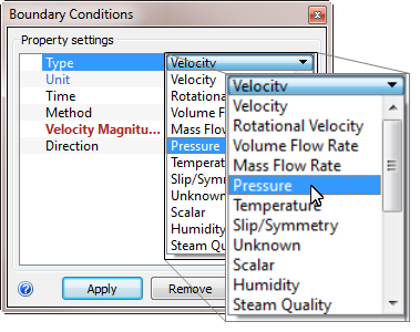
Leave the Unit as Psi and set the Pressure = 0.
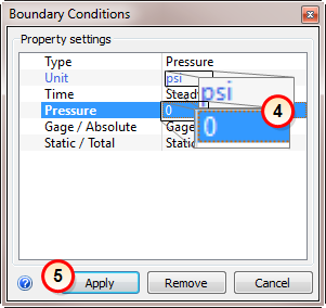
Click Apply.
This defines a static gage pressure of 0, which simulates the flow outlet.
What it should look like...
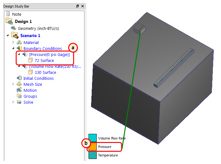
To verify that the boundary condition is correctly applied to the outlet, check the Design Study Bar and the colored stripe on the outlet surface:
On the Design Study bar, the Pressure condition should appear with a value of 0 psi.
There should be a colored stripe on the outlet face that corresponds to the legend.
