External Compressible Flow
External compressible flow can be classified into two categories:
- Aerodynamic applications that are in open air (either at altitude or sea-level)
- Aerodynamic applications in a wind-tunnel.
Unlike internal flows, both types involve flow that passes over and around a device (instead of through it). Examples include flow over a wing, missile, or aircraft nacelle.
The strategies for solving open-air and wind tunnel analyses differ slightly in the domain size and typical inlet condition.
Compressible Open-Air Flow
For open air applications, the solution domain is not defined as part of the model (unlike a wind-tunnel). There are some basic guidelines that drive the size of the domain based on the dimensions of the device. These are only guidelines, and are subject to some variability depending on the circumstances.
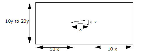
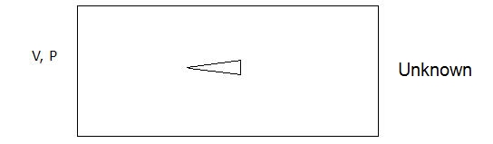
- Inlet: Apply the Velocity (of the object) and static pressure (P = 0) (Total temperature if solving for heat transfer).
- Outlet: Specify the Unknown condition
- If the domain height is less than 20y (see above), then specify a slip condition on the far-field boundary. If the boundary is 20y or more, then either leave the far-field boundaries unspecified, making them walls, or assign the free-stream velocity. The latter will help develop the flow quicker, but will cause convergence problems if a shock hits it.
- To use the correct material properties at altitude, modify the Environment Pressure (and Environment Temperature if heat transfer is of interest). (Right click on the Material branch of the Design Study bar, and select Edit environment reference...). The formula below shows how to calculate reference pressure and temperature at altitude:
-1000 ft < hp < 36,000 ft:
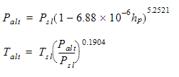
hp = altitude in feet;
Palt = static pressure at altitude
Talt = static temperature at altitude
Psl = pressure at sea level
Tsl = temperature at sea level
36,000 ft < hp < 65,000 ft:
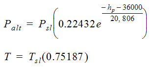
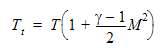
If not solving for heat transfer, be sure to specify the total temperature on the Solve task dialog. Total Temperature is computed using this equation:
Compressible Wind-Tunnel Flow
The inlet is typically fed from a blow-down tank.
Inlet: Specify total pressure (Pt). (The total pressure will be the static pressure of the non-moving air within the tank.) If the velocity is known, specify it as well.
Outlet: Specify static pressure (P = 0)
Specify the Environment Pressure to be the ambient pressure in the wind-tunnel:
- On the Design Study bar, right click on the Material branch, and select Edit environment reference....
- Specify the Pressure on the Material Environment dialog.
For heat transfer, specify the total temperature at the inlet.
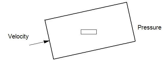
Angle of Attack
If the object has an angle of attack relative to the flow, it is better to re-orient the calculation domain instead of the object. The domain orientation should be that the free-stream velocity and the domain sides are parallel:
Material Environment
For all cases, select Variable on the Material Environment dialog:
- On the Material quick edit dialog, click Edit on the Environment line. (Alternatively, right click on the material name branch in the Design Study bar.)
- Select Variable on the Material Environment dialog.
Simulation Recommendations
We recommend these techniques to improve accuracy of the drag calculation:
The region around the object must be meshed with a very fine mesh. More streamlined bodies require the mesh near the stagnation point of the body to be highly refined to capture the rapidly changing coefficient of pressure.
Invoke the SST k-omega turbulence model:
- Open the Solve dialog, and click Turbulence on the Physics tab.
- From the Turb. model menu, select SST k-omega.
Specify at least 10 layers on the Wall Layers dialog:
- Click Setup > Setup tasks > Mesh Sizing.
- From the context menu, click Wall Layers.
- Drag the Number of layers slider to 10.
Invoke the ADV5 advection scheme:
- Open the Solve dialog, and click Solution control on the Control tab.
- On the Solution Controls dialog, click Advection.
- Select ADV 5 from the list.
Enable Mesh Adaptation. This option progressively refines the mesh over the course of several iterations of the simulation. The result is a mesh-independent solution. Note that this option can be computationally intensive, and can take longer than a single execution of the mesh.
- Open the Solve dialog, and click the Adaptation tab.
- Check Enable Adaptation.
Related Topics