Surface Parts
Surface Parts are two dimensional surfaces incorporated into three dimensional geometry. They are typically used to simulate very thin objects such as guide vanes or sheet metal that the flow must pass around.
Surface Parts are useful because they eliminate the need to model very thin geometry with three dimensional volumes. Meshing such volumes can be very difficult and can result in very large model sizes. The reason is that an element that is small enough to represent the thickness will be so small that a huge number of them are required across the other dimensions of the object. By representing such objects only with surfaces, the elements only need to be small enough to represent the shape of the object, eliminating the thickness from the model.
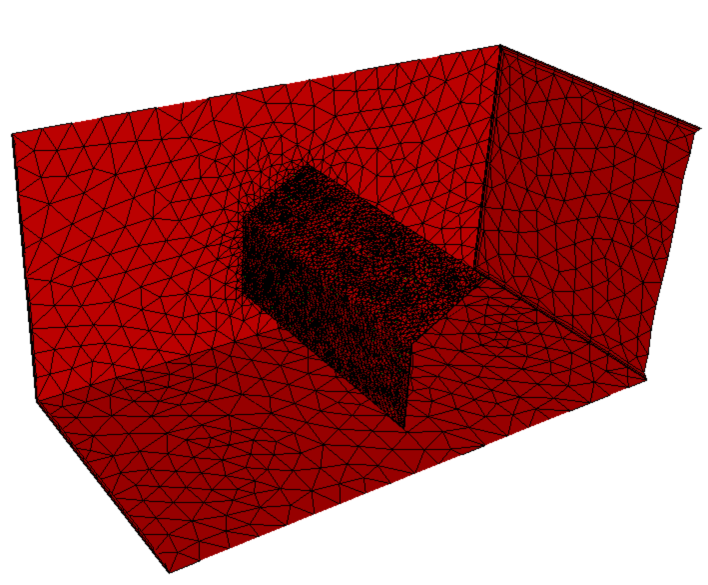
The following model contains a thin-walled obstruction that is modeled as a volume. The element size needed to represent this volume is quite small (because the part is so thin), so the element count is large (about 158,000 elements).
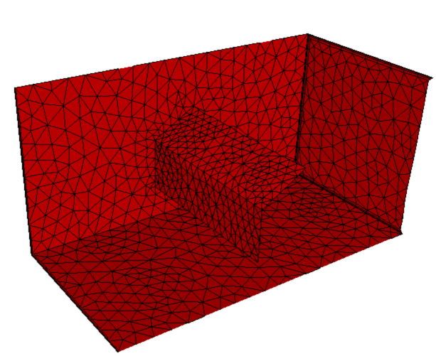
This model, however, uses a Surface Part to represent the thin obstruction. The element size on the surface part is not vastly different from that of the surrounding air, and the overall element count (model size) is considerably smaller (about 38,000 elements):
Another application for Surface Parts is the analysis of thin-bladed turbomachinery devices using Rotating Regions. Surface Parts can greatly simplify the modeling of thin sheet-metal fan blades.
Instead of meshing around very thin three-dimensional blade volumes, represent the blades as surfaces within the rotating region, and assign a Surface Part material to them.
To Assign Surface Parts
Select Surface as the Selection type (either from Setup (tab) > Selection (panel) or by right clicking, and selecting Surface as the Selection mode).
Select the surfaces from the model.
Open the Material quick edit dialog. (Click Edit from the Materials context panel.)
Set the Type to Solid.
Select or create a solid material.
Specify a Shell Thickness.
Select the units for thickness.
Click Apply.
Note: The Shell Thickness value is required, but is only used in the calculation of conduction heat transfer. The thickness value will not modify the geometry in any way, and there will be no graphical representation of the thickness value.
Surface Parts on Surfaces of Volumes
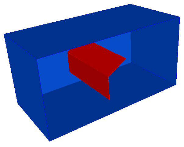
In some situations, it is easier to include a volume within an assembly, and assign one or more surfaces to be Surface Parts. The part is a fluid, and the surface or surfaces are solids which block the flow.
A surface that is part of a volume:
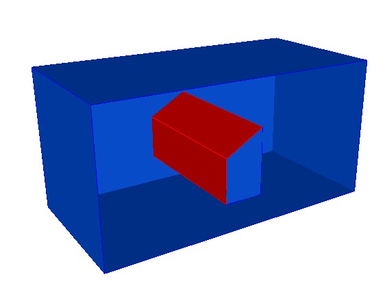
The volume is assigned a fluid material, but because the two front surfaces are assigned a solid material, they are considered to be Surface Parts, and will obstruct the flow:
When assigning Surface Parts to represent an epoxy layer in an electronic chip set, it is not necessary to create a separate surface in the CAD model. Simply select an appropriate surface on one of the chips, and assign a solid material to it. The thermal resistance and the physical thickness are then included in the analysis, without having to complicate the geometry with very thin volumes or creating a huge finite element mesh.
For more about thermal applications for surface parts
Assigning Surface Parts Using CAD Surface Features
Surface parts are always assigned to surfaces. In many cases, it is practical to construct floating surfaces within the three dimensional model. Some CAD tools allow such surfaces to be separate components in an assembly. Others require that these surfaces just be features within a part. An example of a surface feature or part is shown:
The surface is not part of a closed region, but if a solid material is assigned to it (as described above), it will obstruct the flow:
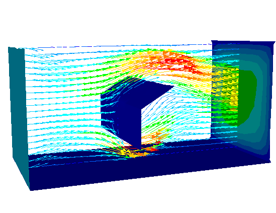
Visualizing Surface Parts
The standard visualization tools in Autodesk® CFD work with Surface Parts. Cutting planes and iso surfaces will display results caused by the presence of Surface Parts. Probe results by hovering the mouse over the area of interest.
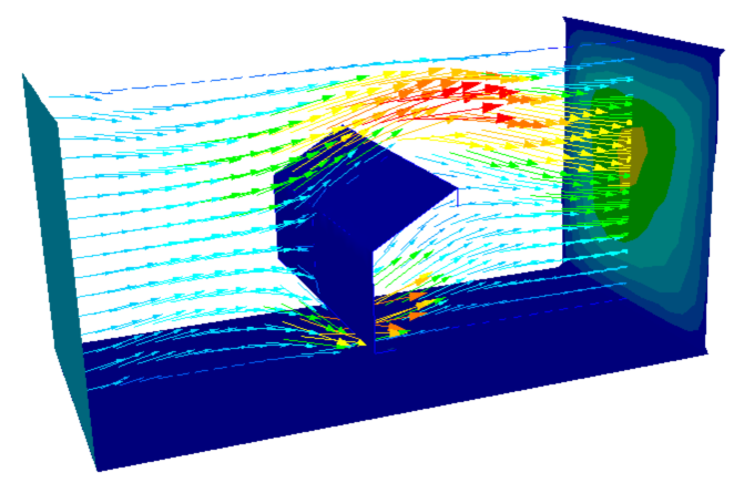
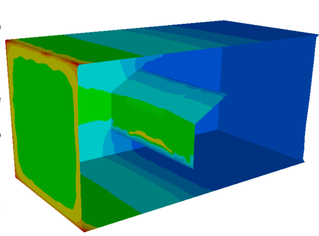
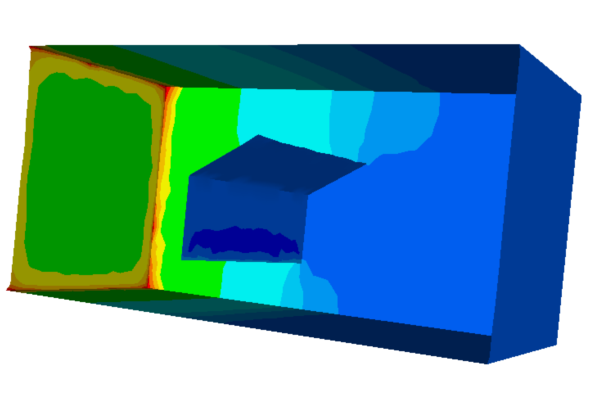
The displayed value of pressure on Surface Parts depends on which side of the Surface Part is viewed. The leading side of a Surface Part will show high pressure, and the wake side will show lower pressure:
When visualizing results, Surface Parts are listed in the Feature Tree under the Materials branch. They are listed separately from volume parts--even those with the same material. Surface Parts can be used as the source surfaces for non-planar cutting surfaces. This is discussed in more detail in the Results Visualization chapter of this manual.
Wall results are assessed on Surface Parts by selecting the appropriate side of the surface. In the example above, selecting the leading side would show a higher wall force than selecting the drag side.