Using Heat Sink Materials
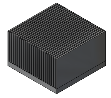
You have a large electronics system to model, but the system contains heat sinks with high fin counts and high fin aspect ratios. You soon realize that including the actual heat sink geometries in your model requires millions of elements for accurate simulation. Fortunately, you have another alternative - the use of heat sink materials. With heat sink materials, you simulate both the fluid and heat flow characteristics of your heat sinks without the need for computationally intensive meshes.
The following sections provide you with the basic procedures for creating and assigning heat sink materials. To find out more details about heat sinks, including guidelines for their use, visit Heat Sinks. To view an example workflow, visit Heat Sink Material - Micro Channel Example.
To Assign an Existing Heat Sink Material
Left-click on the part, and click the Edit icon on the context toolbar to open the Materials quick edit dialog.
Select the appropriate database from the Material DB Name menu.
Select Heat Sink from the Type menu.
Select the material from the Name menu.
Click on the numerical value associated with the Approach Surface. If you know the numerical value of the surface, key in the value. Otherwise, click Select Surface in the Approach Surface dialog. Then, click the appropriate surface on your part.
Note: The Approach Surface is the surface normal to the oncoming fluid flow.Click the numerical value associated with the Base Surface. If you know the numerical value of the surface, key in the value. Otherwise, click Select Surface in the Base Surface dialog. Then, click the appropriate surface on your part.
Note: The Base Surface is the bottom surface of the heat sink material.Click Apply.
To Create or Edit a Heat Sink Material
You can create new Heat Sink materials from scratch, or copy and customize an existing Heat Sink using the Material Editor.
Open the Material Editor.
- Click Material Editor on the Materials context panel.
- Alternatively, if you are in the Materials dialog, click Edit... on the Material line.
Click the List button.
You can work with new or existing materials.
- To create a material, right-click a custom database folder and select New material > Heat Sink.
- To copy an existing material from the read-only Default database, right-click the material to copy and select Save to > <custom database>.
- To copy an existing material from a custom database, click the material to copy and edit the appropriate values.
Specify a Name.
Click the appropriate Properties button to select and define values characteristic of your heat sink. Unsure of your options? Visit Heat Sinks to view modeling guidelines.
Base thickness
Define the thickness of the base to which the fins are attached. Use the actual value for your component if your heat sink has a thin base. If you have a thick base and are modeling the heat sink as two parts, use 0 for the thickness. Click Apply.
Base conductivity
Set the conductivity value for the base and click Apply.
Fin conductivity
Set the conductivity value for the fins and click Apply.
Type
Select the Variation method that best represents your heat sink component, enter appropriate values, and click Apply.
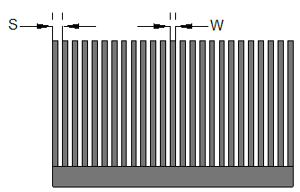
Micro Channel
Specify the following:
Periodic Spacing (S) between fins.
Width (W) of the fins.
Number of fins.
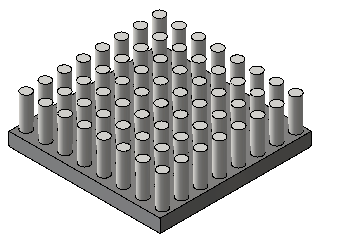
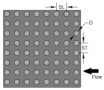
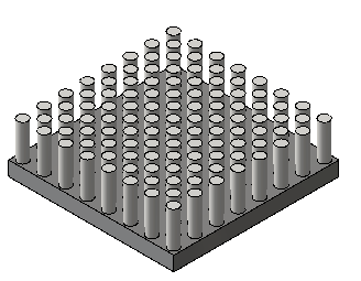
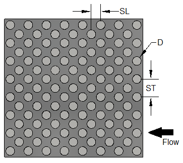
Pin-Fin in Line or Pin-Fin Staggered
Specify the following:
Flow direction spacing (SL).
Number of pins (in a row) in the flow direction.
Normal direction spacing (ST).
Number of pins (in a row) in the direction normal to the flow.
Diameter (D).
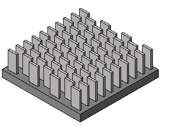
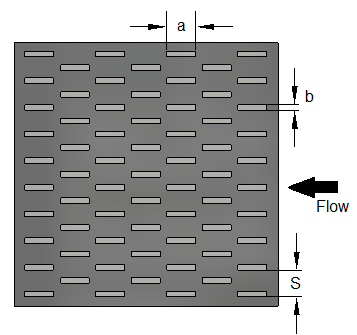
Offset Strip
Specify the following:
Flow direction length (a).
Number of fins (in a row) in the flow direction.
Normal direction width (b).
Normal direction spacing (S).
Number of fins (in a row) in the direction normal to the flow.
Heat Sink Profile
Specify the following based on your data:
- Approach Velocity
- Thermal Resistance
- Friction Factor
Click OK. The new material is available when you open the Materials quick edit dialog.