Geometry Modeling Techniques for AEC Applications
By nature, AEC geometry is very complicated and incorporates a wide range of geometric elements. Several considerations must be made for any AEC application to ensure simulation efficiency, accuracy, and analysis performance.
In this topic, several references are made to Revit, but the basic techniques that are described are applicable to any CAD tool. Additional techniques are presented on the Customer Portal.
Model Complexity
Well-formed geometry with an appropriate level of detail is essential for an efficient AEC simulation. Architectural geometric models often include features that span a wide range of length scales. Consider the effect and relevance of small geometric features on the overall simulation, and remove as necessary to maintain simulation efficiency.
A detail item that is 1/8” long embedded in a 10,000 square foot interior space will require mesh elements that are significantly smaller than the surrounding air volume. If the item is included, the resulting model size is much larger due to the large element count, and run-times are much longer as well.
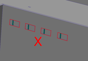
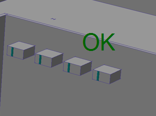
For example, this model contains a large number of site and architectural details:
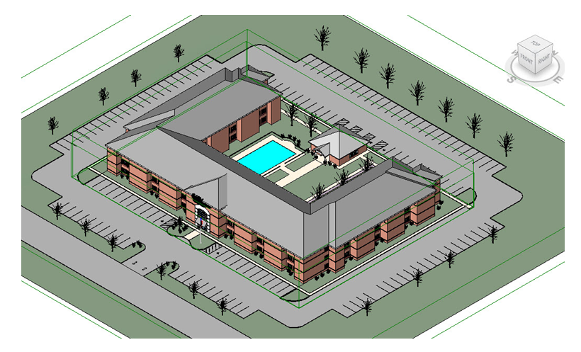
While technically possible to include this level of detail in the Autodesk® CFD model, the model size would be prohibitively large, and these features would not significantly affect the overall results. Before transferring such a model into Autodesk® CFD, it is a good idea to simplify the geometry and remove extraneous details. The analysis-ready version of this model looks like this:
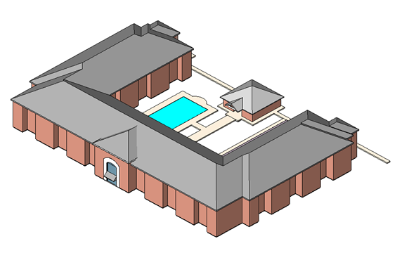
Level of Detail
Many small details that are essential to the design model are not necessary for the Autodesk® CFD simulation. Prior to transferring the model into Autodesk® CFD, use the following techniques to reduce the geometric complexity in the Revit model:
- To exclude features from the simulation model, hide Elements from a 3D View. Elements hidden from the active 3D view in Revit are not transferred into Autodesk® CFD.
- Remove or simplify small features on furniture or detailing.
- Either exclude or substitute features such as small diameter tubing, rounds, fillets, holes, handles, and railings with a simpler representation.
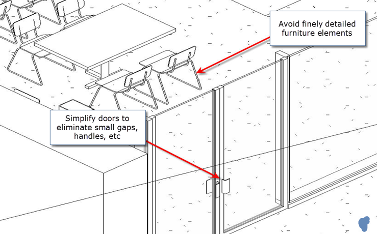
- To quickly hide multiple objects in Revit, right click and select Select All Instances.
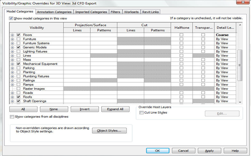
- To disable multiple categories, use Visibility Graphics (shortcut “VG”):
- To exclude unnecessary sections of large building models, use the Section Box tool.
Model Integrity
Before transferring the model into Autodesk® CFD, inspect it closely for interferences and small gaps. The following techniques reference Revit commands, but the strategy can be applied to any CAD tool.
Ensure walls, floors, and ceilings meet cleanly. Avoid small overlaps or gaps.
This prevents a high concentration of very small elements where these features meet.
To review details of the construction, use the Thin Lines view option.
To ensure walls are cleanly lined up, use the Join and Align commands.
Avoid small interferences and gaps between structural elements (such columns and beams) and neighboring geometry.
In the image, small interferences exist between structure and cladding around the outside of the column and beams:
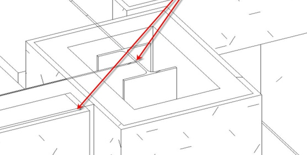
- A simple way to avoid the interferences in this situation is to hide or remove the structural elements from the CAD model.
Associativity
- Part names: Family Categories, Family Names, and Types assigned in the Autodesk® Revit model appear as part names in the Autodesk® CFD Design Study bar. This improves the consistency between the Simulation and BIM models, and enables the use of Rules for assigning materials and boundary conditions to large numbers of geometric entities.
- Parametric Associativity: Settings are maintained more rigorously than in previous versions as the design geometry is cloned and updated. This improves the Design Study process by preserving associativity between applied conditions and the geometric model as the design is modified.
Create the Air Volume
A dedicated air volume is needed in any analysis that simulates the flow of air. Most AEC CAD models only include the physical solids, so an additional step is required to create the flow region. There are a three primary ways to create an air volume:
Method 1: Ensure the volume is "air tight"
Autodesk® CFD automatically replaces all completely enclosed cavities with internal volumes when the model is transferred from CAD.
- These volumes are listed in the Design Study bar, and are a part of the simulation model.
- Assign Air to these volumes.

Trouble-shooting tips if the flow volume is not created
If the model appears "water tight," but no volume is generated after transferring into Autodesk® CFD, there is likely a gap, hole, or opening somewhere in the geometry. Use these techniques to identify the location of the problem:
Visual Inspection
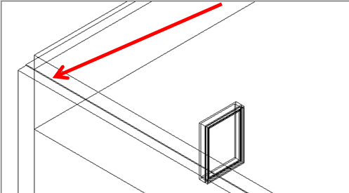
- Check for gaps using the 3D View and Plan Views. Edges that appear closely bunched together often indicate a gap.
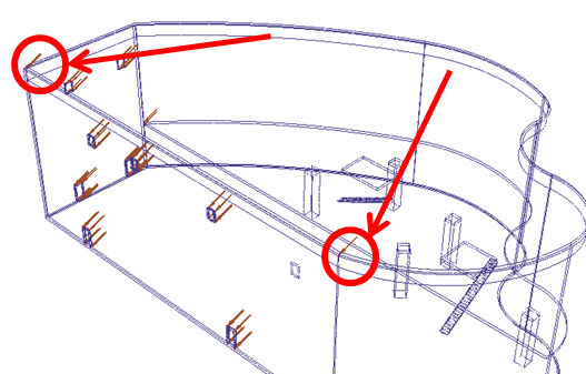
- Use the Autodesk® CFDMesh Diagnostics tools to identify small surfaces and short edges. Such features may indicate the location of gaps between floors and walls:
Create a Test Mesh
Long, thin gaps are usually meshed with long, skinny elements. The areas in the model with the highest values of Nodal Aspect ratio are likely where the gaps are. This procedure is summarized:
- Create a volume around the entire model with the External Volume Geometry tool in Autodesk® CFD.
- Assign a solid material to all parts in the model. Assign Air to the surrounding volume.
- On the Solve dialog, click Results quantities, and enable Stream Function. (This enables nodal aspect ratio as an output quantity.)
- To generate the mesh, set the number of iterations to 0 on the Control tab of the Solve dialog,, and click Solve.
- After the mesh is complete, create an Iso Surface, and show Nodal Aspect Ratio. The regions with the highest Nodal Aspect Ratio are often the gaps.
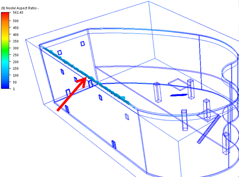
After finding the gaps, eliminate them by aligning the mismatching features in the CAD model.
Method 2: Use the Autodesk® CFD Void Fill tool
After transferring the model into Autodesk® CFD, use the Void Fill tool to cap the openings and fill the resulting cavity. To open the Void Fill dialog:
- Right click on the Geometry branch of the Design Study bar
- Click Edit....
- Select the Void fill tab of the Geometry tools dialog.
Assign Air to volumes created with the Void Fill tool.
Method 3: Create the air part in the CAD model
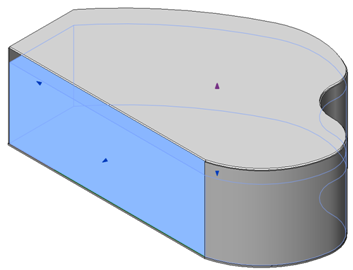
- In many architectural models, it is possible to extrude a volume from the floor to the ceiling to fill the interior space.
- After transferring the model to Autodesk® CFD, assign Air to the volume.
Inlet Extensions for Heat Transfer Boundary Conditions
To ensure enough space between the boundary conditions and the internal flow, it may be necessary to extend the openings in the CAD model.
- This is useful for flow-only analyses, but is essential when temperature boundary conditions are applied to openings. This practice ensures adequate distance between the opening and the neighboring walls whose temperatures are not known.
- This technique helps prevent the boundary condition from artificially affecting the temperature distribution on the walls and adjacent solid parts. The result is improved accuracy of the temperature solution.
Extend the opening at least the hydraulic diameter of the surface:
 |  |