To add a fixed vertical straight with two points
Add a fixed vertical straight by specifying two points that the line will pass through.
- Click the profile. Click
 Find.
Find. - On the Profile Layout Tools toolbar, click
 Draw Fixed Straight By Two Points.
 - Specify the start point.
- Specify the next point.
To add a fixed vertical straight by best fit
Add a fixed, two-point vertical straight element by best fit to a profile. You can define the best fit element using a series of Autodesk Civil 3D points or clicks on screen.
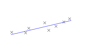
The following illustration shows a fixed vertical straight created by best fit. The Xs indicate the data points that were used to create the element.
Note: Each best fit profile element is drawn to the vertical scale set in the profile view style. To create an accurate best fit element, set the profile view style Vertical Exaggeration value to 1.000 to match the horizontal scale of the profile view.
- Set the profile view style Vertical Exaggeration value to 1.0000.
- Click the profile. Click Find.
- On the Profile Layout Tools toolbar, click
 Fixed Straight - Best Fit.
 - In the Straight by Best Fit dialog box, select one of the following:
- From COGO Points. In plan view, select two or more points. Enter G to select a point group or N to enter points by number.
- By Clicking On The Screen. Select a starting point and at least one other point. You can use OSNAP or transparent commands to select points.
- From Elements. Specify the tessellation and mid-ordinate tolerance settings. You can select one or more of the element types listed on the command line. If you selected a profile element, specify the starting and ending station on the Specify Station Range dialog box.
- In the Panorama window, use the Regression Data vista to modify the regression points.
As you highlight a row in the Regression Data vista, the corresponding regression point in the drawing window is highlighted in red.
- Create the straight:
- Click
 to create the straight and keep the Regression Data vista open.
 - Click
 to create the straight and close the Regression Data vista.
- Click