Part matching when round-tripping pipe networks with Autodesk Civil 3D is accomplished with the use of import and export settings and a part mapping XML file.
This topic contains the following sections:
Part Matching Solution Overview
Changes to Part Types in the STM file
Storm Sewers (STM) File Properties
Part Matching Introduction
This topic addresses workflows and methods for integrating Autodesk Civil 3D with Autodesk analysis applications, mainly Autodesk Storm and Sanitary Analysis. The main focus is on importing Autodesk Civil 3D pipe network data into Storm and Sanitary Analysis and importing it back again into Autodesk Civil 3D. Some of this information applies to integration with Hydraflow Storm Sewers as well.
Autodesk Storm and Sanitary Analysis enables you to model stormwater networks using various hydrology and hydraulic computational methods; it can also be used to model sanitary sewer networks. This topic describes the features in the product that enhance its integration with Autodesk Civil 3D.
Part Matching Workflow
There are a variety of ways to perform stormwater analysis. The following workflow uses the stronger abilities of each product to best perform a design.
Creating pipe and structure elements in Autodesk Civil 3D instead of in Storm and Sanitary Analysis can take advantage of other model elements in a way that Storm and Sanitary Analysis can not. However, true hydrology and hydraulic properties are more appropriately entered in Storm and Sanitary Analysis.
The workflow addressed in this topic outlines the following process:
- Creating pipe networks in Autodesk Civil 3D to be analysed in Autodesk Storm and Sanitary Analysis.
- Making changes to the network in the analysis application.
- Moving the data back into Autodesk Civil 3D.
This process enables you to make best use of each product and perform round-tripping for multiple design iterations. In the process of moving data between applications, you will not want to lose data unnecessarily along the way, and this topic discusses the settings and features that are available that preserve your pipe data definitions during round-tripping.
Issues When Transferring Pipe Network Data between AutoCAD Civil 3D 2011 and Storm and Sanitary Analysis
- The system for moving data between AutoCAD Civil 3D and Storm and Sanitary Analysis uses an existing STM (Storm Sewers) file format. The existing Storm Sewers Migration settings only allow for matching to a limited number of pipe and structure types. This makes it nearly impossible to provide one-to-one matching with either AutoCAD Civil 3D or Storm and Sanitary Analysis parts.
- The matching of Storm and Sanitary Analysis parts to parts from the Storm Sewers file is "hard-coded". Because you cannot choose which Storm and Sanitary Analysis part types to use, you currently need to manually redefine the part after transfer.
- Inlet structures created in AutoCAD Civil 3D do not currently have the data necessary for Storm and Sanitary Analysis to define direct mapping between the products.
- The properties for AutoCAD Civil 3D structures describe the "body" and certain properties about the frame of the inlet for the parts.
- The properties for Storm and Sanitary Analysis inlets have no data describing the "body" of the parts, and have a more elaborate data scheme for describing the inlets for the parts.
- For pipes, the properties for AutoCAD Civil 3D pipes describe properties that are not described in Storm and Sanitary Analysis pipe conveyance links, such as pipe material.
- The limitations of the STM file mentioned above may also cause it to appear that an AutoCAD Civil 3D part has been changed and data is lost because the appropriate part family is not able to be properly resolved and for a given part the part family is then swapped. For example, PVC and Concrete circular pipes are exported to STM, analyzed in Storm and Sanitary Analysis and brought back to AutoCAD Civil 3D through the STM file. AutoCAD Civil 3D tries to set both pipe types to the one part family that matches the circular pipe's Import Matchup Setting. So if circular pipes are set to match to the Concrete circular pipe part family, all of the PVC circular pipes will be swapped to Concrete circular pipes.
Note: For an example of this, see Import and Export Part Matching Example.
- Culverts (pipes with a headwall or end section on the uphill side) are imported to Storm and Sanitary Analysis as regular pipes, and there is no way to define the culvert type or entrance type in AutoCAD Civil 3D so it does not import automatically as a culvert into Storm and Sanitary Analysis. In Storm and Sanitary Analysis culverts have entrance conditions that get set.
Part Matching Solution Overview
- Autodesk Civil 3D 2024 and Storm and Sanitary Analysis 2024 will still transfer data through the STM file, but an additional XML file will be used by Storm and Sanitary Analysis for part mapping. Autodesk Civil 3D will write Part IDs to the STM file for both pipes and structures. The XML part mapping file will list these Part IDs followed by the desired Storm and Sanitary Analysis element and attribute information. Experienced users will be able to modify the part mapping file so that:
- They can map any standard or custom Autodesk Civil 3D Part ID to the Storm and Sanitary Analysis elements they use.
Note: The "Part ID" is a globally unique identifier (GUID) associated with each Part Family created in Autodesk Civil 3D. It is unique for each Part Family and the same for all sizes within the same Part Family. This ID can be found in the Part Family's XML file and is also exported to STM files.
- They can map to Storm and Sanitary elements using dimensional properties.
- They can map any standard or custom Autodesk Civil 3D Part ID to the Storm and Sanitary Analysis elements they use.
- A Autodesk Civil 3D pipe part family can be mapped to a Storm and Sanitary Analysis culvert part with desired entrance conditions set.
- Storm and Sanitary Analysis will import Hydraflow Storm Sewers (STM) files, locating the Part ID within the STM files. Storm and Sanitary Analysis will then map the Part ID to a Storm and Sanitary Analysis part based on the pairing within XML part mapping file.
- Storm and Sanitary Analysis will also export Part IDs to an STM file.
- Hydraflow Storm Sewers will ignore Part IDs in the STM file but will store the values so they can be re-used when imported to either Autodesk Civil 3D or Storm and Sanitary Analysis. Hydraflow Storm Sewers will not use the XML part mapping file.
- A property has been added to the Autodesk Civil 3D Structure Part Properties in order to define an Inlet Location as either "On Gradient" or "On Sag". This property will be transferred to the STM file to allow Storm and Sanitary Analysis parts to be selected based upon this condition.
- A Feature Setting has been added to Autodesk Civil 3D so that you can control the use of the Part ID upon import.
- An additional Feature Setting has been added to Autodesk Civil 3D so that you can choose not to swap pipe network parts when importing data through a STM file.
Transferring Data
A command, Edit in Storm and Sanitary Analysis, has been added to Autodesk Civil 3D which simplifies pipe network data transfer.
This command can be found on the Design panel of the Analyze tab on the ribbon, and also on the Pipe Network contextual ribbon.
Edit in Storm and Sanitary Analysis prompts you to select a pipe network and then the command transparently exports the data and current drawing file into Storm and Sanitary Analysis. This command uses the data transfer files and the Part Matching Defaults export settings.
This command creates a temporary Hydraflow Storm Sewers STM file to transfer the data.
To bring data back into Autodesk Civil 3D you can use the File  Export Hydraflow Storm Sewers File command from Storm and Sanitary Analysis and then import that file into Autodesk Civil 3D. This process enables an existing pipe network to be updated with the data from Storm and Sanitary Analysis.
Autodesk Civil 3D uses the Storm Sewers Migration Defaults and either the Part ID or the Import Part Matchup Settings when matching parts, as discussed below in Autodesk Civil 3D Settings for Controlling Part Matching.
Autodesk Civil 3D Properties for Specifying Inlet Type
Autodesk Civil 3D pipe network structures have been enhanced to contain a Inlet Location property. The new Inlet Location property is available on the Part Properties tab of the Structure Properties dialog box, under Hydraulic Properties.
The values for this property are On Sag, On Gradient or <none>.
This property is written out to STM files from Autodesk Civil 3D for use in Storm and Sanitary Analysis and Storm Sewers.
Autodesk Civil 3D Settings for Controlling Part Matching
Two new settings provide Autodesk Civil 3D additional control when importing from a Storm Sewers (STM) file. These settings are found under Storm Sewers Migration Defaults in the Pipe Network Feature Settings.
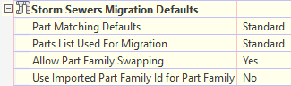
Allow Part Family Swapping
The new Allow Part Family Swapping setting provides the ability to control the behavior of swapping part families when importing a Storm Sewers (STM) file. The default for this setting is Yes to match the behavior of AutoCAD Civil 3D 2011 and prior versions.
Previous versions of Autodesk Civil 3D would automatically swap part families based on part matching with no ability to turn off this behaviour.
With the setting set to No, Autodesk Civil 3D will only use dimensional properties to swap part sizes within the same part family.
With part family swapping set to Yes you may find that some parts in a pipe network change to different Part Families, and previously-assigned optional properties and labels are removed. This would occur when the combination of the part type in the STM file and the associated Part Matching Defaults match to a different part family than what's currently being used in the Autodesk Civil 3D drawing.
For example, this could occur if multiple circular pipes are imported from an STM file into an Autodesk Civil 3D pipe network where there is a mix of concrete and PVC circular pipes. The Part Matching Defaults can only assign one part family for circular pipe, so if circular pipe is matched to the Concrete part family, then all the PVC pipes in the network will be swapped to Concrete.
The default setting of Yes maintains the behaviour of prior Autodesk Civil 3D versions (as described in the above example) by swapping part families of each individual part if the part family in the STM file being imported is different from the part's family in the Autodesk Civil 3D drawing.
Changing the setting to No prevents all part family swapping during STM file import. However, part sizes may be changed within the family based on dimensional values that are imported:
- For pipes, part size swapping is based on diameter (or width and length for non-circular pipes) within the same part family.
- For structures, part size swapping is based on body dimensions and frame dimensions.
Use Imported Part ID for Part Family
The new Use Imported Part ID for Part Family setting controls the mapping of Part Families based on the Part IDs in the STM file. The default for this setting is No to match the behaviour of previous versions of Autodesk Civil 3D.
If Allow Part Family Swapping (described above) is set to Yes, then the Use Imported Part ID for Part Family setting tells Autodesk Civil 3D whether or not to map to Part Families based on the Part IDs in the STM file for each imported part. If Allow Part Family Swapping is set to No, then the Use Imported Part ID for Part Family setting has no effect.
The behavior of Use Imported Part ID for Part Family is as follows:
- A No value will maintain the behavior of AutoCAD Civil 3D 2011 and prior versions by using the Import settings in the Part Matching Defaults to determine the Part Family.
- A Yes value will use the Part ID in the STM file to determine the Part Family to be used for matching. However, if a valid Part ID is not found in the part list used for migration (as specified in the part matching defaults), then that part will use the Import settings in the Part Matching Defaults.
Data Transfer Files
There are two files used during the data transfer from Autodesk Civil 3D to Storm and Sanitary Analysis and from Storm and Sanitary Analysis to Autodesk Civil 3D:
- Storm Sewers file (STM) - specific to each project
- Part mapping file (XML) - globally used file (not project specific)
The STM file is project specific and contains all the nodes and links of the pipe networks in the model. It contains information specific to each instance of the part in the project (for example, levels, diameters, and data specific to the part's location in the model).
A temporary STM file is created transparently with the Edit in Storm and Sanitary Analysis (or Edit in Storm Sewers) command. Or you can use the Export to STM command and save the STM file to a defined location.
The part matching XML file is used by Storm and Sanitary Analysis to map Autodesk Civil 3D parts (using a Part ID) found in a STM file to a Storm and Sanitary Analysis element (Junction, Inlet, Conveyance Link, Storage, Channel, Orifice, Weir and so on). The XML part mapping file is intended to be used globally on all projects so it would only contain data to define a specific cataloged part, and not data that would differ for different instances of the same part (for example, Inlet Location, road & channel slopes).
Changes to Part Types in the STM file
In AutoCAD Civil 3D 2011 and prior versions, only the Hydraflow Storm Sewers part types were exported to the STM file. These included three Line Types (shapes for pipes) and nine Junction Types (for structures) that are configurable from the Storm Sewers Migration Defaults/Part Matching Defaults inside the AutoCAD Civil 3D Pipe Network Feature Settings.
A change was made in Autodesk Civil 3D so that the Part Families's Part ID and Part Description for each pipe and structure are exported to the STM file. This provides the ability to match more parts for analysis rather than being limited to a small number of available Hydraflow Storm Sewers parts.
Autodesk Civil 3D exports the Part ID and description for each pipe and structure to the STM file as follows:
- Pipe Part IDs are exported after the Line Type field to new fields: "Line Part ID" and "Line Part Description".
- Structure Part IDs are exported after the Junction Type field to new fields: "Junction Part ID" and "Junction Part Description".
Example uses of the new fields are shown below with new data displayed in bold:
Pipes:
"Line Type = ","Cir"
"Line Part ID = ","30921980-2D9B-493A-88C5-6D10AEA8B835"
"Line Part Description = ","AeccCircularConcretePipe_Imperial"
Structures:
"Junction Type = ",4
"Junction Part ID = ","112AAC17-CBCB-4B43-838A-2B38C17B3ABC"
"Junction Part Description = ","AeccStructTwoTierRectBase_Imperial"
Storm Sewers (STM) File Properties
Instance-specific data from a project file is exported to the Storm Sewers STM file. The following lists show the STM fields that are used by Autodesk Civil 3D and Storm and Sanitary Analysis to define parts and elements.
For Pipes / Lines / Links:
- Line Length (pipe length)
- Invert Lev Dn (pipe's downstream invert)
- Line Slope (pipe gradient)
- Rise (pipe height)
- Span (pipe diameter or width)
- No. Barrels (number of pipe barrels)
- n-Value (Manning's roughness coefficient)
- Line Type (Storm Sewers pipe type)
- Line Part ID (Autodesk Civil 3DPart Family identifier)
For Structures / Junctions / Nodes:
- Ground / Cover Lev Dn (Cover level of the downstream structure)
- Ground / Cover Lev Up (Cover level of the upstream structure)
- Junction Type (Storm Sewers structure/inlet type)
- Junction Part ID (Autodesk Civil 3D Part Family identifier)
- Junction Part Description (Autodesk Civil 3D Part Family description
- Downstream Inlet No. (structure taking bypass flow)
- Inlet Length (kerb opening length)
- Inlet Throat Height (kerb opening height)
- Grate Opening Area (not used by Autodesk Civil 3D or Storm and Sanitary Analysis)
- Gully Length
- Gully Width
- Known Capacity (sets maximum cutoff value for Generic Inlets)
- Channel Width
- Channel Slope
- Inlet Crossfall Sw (carriageway longitudinal slope)
- Inlet Crossfall Sx (carriageway crossfall)
- Inlet Sag (Inlet Location property value)
- Inlet ID (upstream structure name / ID)
- Local Inlet Depression (depression)
- Channel n-Value (carriageway Manning's roughness coefficient)
The above Line Type and Junction Type values are used for matching to and from Autodesk Civil 3D based upon the Part Matching Defaults settings.
The Part Matching Defaults settings are found in the Feature Settings for Pipe Networks under Storm Sewers Migration Defaults.
Most users find that they get the best results when the Export matchup settings are equivalent to the Import matchup settings. Otherwise, a different Part Family will be substituted upon import.
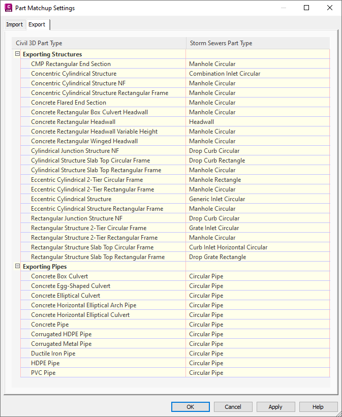
The Export tab as shown below enables you to select any of the available Storm Sewers Part Types (on the right) to match to each of the Autodesk Civil 3D Part Types found in the current Part Catalogue. The Autodesk Civil 3D Part Types that are shown are updated based on changes made to the Part Catalogue.
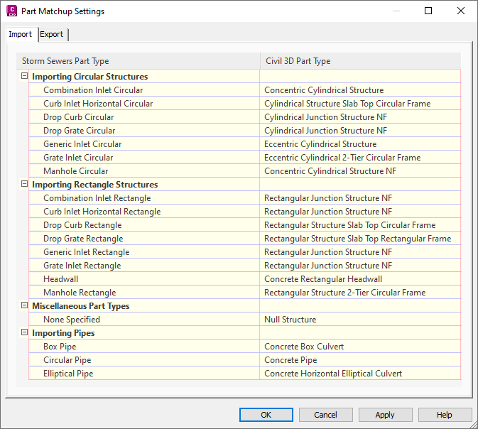
The Import tab enables you to select a Autodesk Civil 3D Part Family (on the right) to be used for each available Storm Sewers Part Type. The Storm Sewers Part Type is a fixed list. This mapping should be equivalent to the export mapping so that part families remain the same.
Most new structures in Storm and Sanitary Analysis will export as a rectangular shaped 4 foot by 4 foot structure in the STM file and may not match the same part types that were originally imported as circular structures (if Use Imported Part ID for Part Family is set to No). One possible practice would be to have rectangular Storm Sewers Parts and circular Storm Sewers Parts map to the same Autodesk Civil 3D Part Type, although if the setting are configured with that strategy, a one-to-one mapping between Storm Sewers Part Type and Autodesk Civil 3D Part Type will not be possible.
The matching of STM Part Type to Storm and Sanitary Analysis Part Type is hard-coded. The following table shows how Storm and Sanitary Analysis uses the values. Reading from left to right shows the STM part types, how they are imported into Storm and Sanitary Analysis, and then how those are exported back to the STM file:
STM Part Types Table
| STM Part Type Exported from Autodesk Civil 3D | Corresponding Storm and Sanitary Analysis Part Type | STM Part Type Imported into Autodesk Civil 3D |
|
Structures
The numerical values shown in parentheses in the first and last columns represent the numerical values found in the STM file. |
||
| Manhole (0) | Junction | Manhole (0) |
| Combination Inlet (3) | Inlet - FHWA Combination Inlet | Combination Inlet (3) |
| Kerb Inlet (1) | Inlet - FHWA Kerb Inlet | Kerb Inlet (1) |
| Gully Inlet (2) | Inlet - FHWA Gully (Rectangular) | Gully Inlet (2) |
| Drop Gully (8) | Inlet - Central Reserve & Ditch Inlet | Drop Gully (8) |
| Drop Kerb (7) | Inlet - FHWA Kerb Inlet | Drop Kerb (7) |
| Generic (4) | Maximum Cutoff Inlet | Generic (4) |
| Headwall (5) | Junction (or Outfall if end of run) | Manhole (0) |
| No Structure (6) | Junction | Manhole (0) |
| Outfall | Outfall | Outfall |
| none | Inlet - FHWA Gully (Circular) | Gully Inlet (2) |
| none | Storage Node | Manhole (0) |
| none | Diversion | Manhole (0) |
| Pipes | ||
| Circular pipe ("Cir") | Conveyance Link - Circular Pipe | Circular pipe ("Cir") |
| Box culvert ("Box") | Conveyance Link - Rectangular Pipe | Box culvert ("Box") |
| Elliptical pipe ("Ell") | Conveyance Link - Elliptical Pipe | Elliptical pipe ("Ell") |
The XML Part Mapping Files
If you need to have more control over part mapping, you can set up an XML part mapping file.
When you use an XML part mapping file, the part mapping is done using the Part ID included in the STM file. The XML part mapping file creates a specific mapping between Autodesk Civil 3D and Storm and Sanitary Analysis parts based on Part ID, so specific matches can be made.
The XML part mapping file is editable and is intended to be used by advanced users to map Autodesk Civil 3D parts to specific Storm and Sanitary Analysis part configurations. The XML part mapping file has a separate format for different element types.
Sample XML Part Mapping Files and Schema Definition File
The default XML part mapping file is installed to the following folder:
C:\ProgramData\Autodesk\SSA <version>\Support\SSA_Mapping_Definition_Civil.XML
This default file is an empty placeholder file so that the prior version's behavior is maintained for users unaware of this available functionality. To use the XML part mapping functionality, you would set up a valid part mapping file. A sample valid file is available in the following path, but it requires customization to meet each organization's standards:
C:\Program Files (x86)\Autodesk\SSA <version>\Samples\Part Matching
The example file included in Storm and Sanitary Analysis provides an entry for each part family that is included by default in Autodesk Civil 3D.
For more detail on the XML format, refer to the SSA_Mapping_Definition schema and description files located in the following folder:
C:\Program Files (x86)\Autodesk\SSA <version>\Samples\Part Matching
A document that describes the schema file is named SSA_Mapping_Definition.docx.
Format of the XML Part Mapping File
The XML part mapping file consists of two sections:
- The Autodesk Civil 3D part section (MatchedPart)
- The Storm and Sanitary Analysis part section (SSAPart)
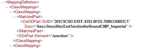
The Autodesk Civil 3D Matched Part portion of the XML file is bounded by a <MatchedPart> begin tab and a </MatchedPart> close tag. For each Autodesk Civil 3D part, or multiple parts, the Autodesk Civil 3D Part ID (part family GUID) and description will be within the matched part construct.
Each Matched Part within a <ClassMapping> element must have a matching singular SSA Part element.
An example of an XML part mapping file is shown below. This example shows the mapping between a custom Autodesk Civil 3D Part Family name "InltKerb1" to a FDOT Kerb Inlet Type 1 found in Storm and Sanitary Analysis.
<ClassMapping>
    <MatchedPart>
      <Civil3DPart GUID = "260FBCAD-7BFC-4DC4-AD9C-84D552C799F5" Desc = "InltCurb1"/>
    </MatchedPart>
    <SSAPart Element = "Inlet">
      <Inlet Manufacturer = "FDOT" PartNumber = "Curb Inlet - Type 1"/>
    </SSAPart>
</ClassMapping>
Using the "Custom" Attribute
The matching SSA Part can be as specific or generic as desired. If a fixed Storm and Sanitary Analysis part does not fit your needs, the use of the Custom attribute with a value of "True" enables you to alter some hard coded part values giving you control of specific settings within Storm and Sanitary Analysis.
XML Part Mapping File Matching Process
Import process
- When Storm and Sanitary Analysis imports an STM file, it compares the Part IDs in the STM file to the Part IDs in the XML part mapping file.
- Storm and Sanitary Analysis then uses the indicated Storm and Sanitary Analysis Part in the XML file to create and define the element.
- The Part ID is cached for the element in the Storm and Sanitary Analysis file for subsequent use exporting to a Hydraflow Storm Sewers file. If the Part ID found in the STM file is not found in the XML part mapping file, then the Line Type and/or Junction Type values found in the STM file will be used.
Export process
- When Storm and Sanitary Analysis exports to an STM file, it checks for the Storm and Sanitary Analysis part type in the XML part mapping file for each element.
- Storm and Sanitary Analysis then writes the corresponding Part ID to the STM file if a match is found.
Note: In cases where there are duplicate matches for the same Storm and Sanitary Analysis Part configuration, Storm and Sanitary Analysis will use the initial cached Part ID if it is one of the matches. Otherwise Storm and Sanitary Analysis will use the first match found in the part mapping XML file. Therefore, the order in the part mapping XML file can be an important consideration.
- If a match cannot be found, then a Part ID is not written to the STM file for that element.
When Autodesk Civil 3D imports data from a STM file, the part matching behaviour is based on the Autodesk Civil 3D Settings for Controlling Part Matching.
Customizing an XML Part Mapping File
The XML part mapping file can be edited with Notepad or an XML editor. Only the contents of the ClassMappings tag should be edited. The individual mappings are each contained within the singular ClassMapping tags (see example below).
For each part to be mapped, the schema requires attributes for the Autodesk Civil 3D Part, followed by the Storm and Sanitary Analysis Part.
The Autodesk Civil 3D Part requires the GUID (Part ID), followed by the Description (the description is used to make the file easier to read, but it's not actually used in matching).
Create Design Set Pipe Network Catalogue). The default path for the Part Catalog is: C:\ProgramData\Autodesk\C3D <version>\eng\Pipes Catalog\. For more information, see To Specify the Pipe Network Part Catalog.
Below is an example showing a Part ID (in bold text) for the Imperial Concentric Cylindrical Structure which is found in the following subfolder and file: …\US Imperial Structures\Junction Structures with Frames\ AeccStructConcentricCylinder_Imperial.xml
<ColumnConst desc="Part ID" dataType="string" unit="" name="PrtID" id="CC5" visible="0" context="Catalog_PartID"index="0">CFDB68E2-8070-4463-8BA0-F44037BAF991</ColumnConst>
The Storm and Sanitary Analysis Part requires the element type, optionally followed by attributes that will vary depending on the element being matched. Be sure to match Autodesk Civil 3D Pipe families to Storm and Sanitary Analysis Link elements and Autodesk Civil 3D Structure families to Storm and Sanitary Analysis Node elements.
| Storm and Sanitary Analysis Node Elements | Storm and Sanitary Analysis Link Elements |
|
Junction |
Conveyance Link |
|
Inlet |
Pump |
|
Storage |
Orifice |
|
Outfall |
Weir |
|
Flow Diversion |
Outlet |
The following examples show Autodesk Civil 3D parts that are matched to different types of Storm and Sanitary Analysis parts. The bold items are the attributes that should be edited to make the proper matching. The items in red are the schema tag names and would likely not change for the same element type.
This format could also be used for most of the other elements, except Inlets and Conveyance Links. For example, you could replace "Junction" with the desired element type, such as "Storage", "Outfall", "FlowDiversion", and so on.
Junctions (or other nodes)
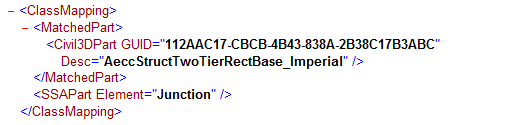
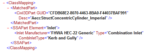
Combination Inlet
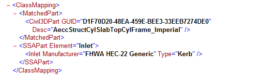
Kerb Inlet
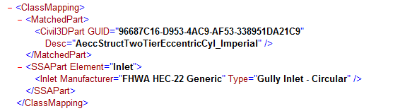
Gully Inlet
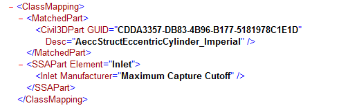
Maximum Capture Cutoff
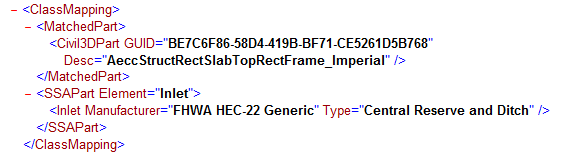
Central Reserve & Ditch Inlet
Conveyance Link: Pipe
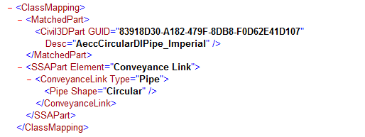
The Conveyance Link Type could include: Pipe, Open Channel, Culvert, or Direct.
The shape will vary depending on the type chosen (refer to available shapes for each type inside Storm and Sanitary Analysis.)
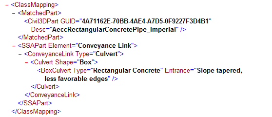
Conveyance Link: Culvert (with culvert type and entrance attributes)
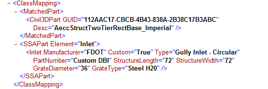
Special Case: Custom Inlets
The Inlet element in Storm and Sanitary Analysis is a special case since there are additional "dimensional" attributes that could be used to map to a more specific cataloged part. More information is available in the SSA_Mapping_Definition.docx file mentioned above. Be sure to use the appropriate attributes for the specific part in Storm and Sanitary Analysis that you are mapping to.
Example: (this example maps to a custom FDOT circular gully with custom attributes)
Special Case: Outfalls
Outfalls are not addressed by the solution because they do not have a part ID associated with them. In an STM file the last, most downstream node is an outfall, and outfalls do not have any properties in the STM file. The outfall nodes cannot be assigned a JunctionType or GUID in the STM file. This is not an issue for Storm and Sanitary Analysis since these will simply be imported as Storm and Sanitary Analysis Outfalls. However, when importing the data back into Autodesk Civil 3D, the outfall will use the Part Family assigned to "Headwall" on the Import tab of the Part Matching Defaults Feature Settings.
Import and Export Part Matching Example
The following sections use a simple example to explain the part mapping system and settings.
Exporting Pipes from Autodesk Civil 3D
The following scenario starts with creating two pipes of different types in your drawing, and then exporting to an STM file and examining the properties of that file.
- For the purposes of this example, create two unconnected pipes in Autodesk Civil 3D using the Storm Sewers part list with Null structures:
- 12 inch Concrete Pipe
- 4 inch Corrugated HDPE Pipe
- Open the Pipe Network Feature Settings dialog box and examine the Part Matchup Settings. On the Export tab:
- The Concrete pipe is mapped to Circular Pipe
- The HDPE pipe is mapped to Circular Pipe
This means that both pipe types will be exported to the Circular Pipe type.
- On the Import tab, under Importing Pipes, Circular Pipes can only match to one type, "Concrete Pipe."
This means that by default, circular pipes that are not concrete, such as the Corrugated HDPE pipe, will be switched to Concrete on import. The following example shows how to set up the XML part mapping file so the pipe type is retained on import.
- Ensure that the Use Imported Part ID for Part Family setting is set to Yes.
- Ensure that Allow Part Family Swapping is set to Yes.
- Export the pipes to an STM file.
- Open the STM file in a text editor and examine its properties.
- The concrete pipe appears as follows:
"Line Type = ","Cir"
"Line Part ID = ","30921980-2D9B-493A-88C5-6D10AEA8B835"
"Line Part Description = ","AeccCircularConcretePipe_Imperial"
- The HDPE pipe appears as follows:
"Line Type = ","Cir"
"Line Part ID = ","864CAB49-5CD4-47E7-978B-A0E9D6B8107C"
"Line Part Description = ","AeccCircularCorrugatedHDPEPipe_Imperial"
Tip: Exporting your pipe network to an STM file is a quick way to identify the part IDs required for the XML part mapping file. - The concrete pipe appears as follows:
- Examine the STM Part Types Table in this topic.
Note that the Line Type above, Cir, will by default map to Conveyance Link - Circular Pipe.
Importing into, and Exporting Out of Storm and Sanitary Analysis Without Mappings Set Up in an XML Part Mapping File
The following scenario continues from the above steps and assumes you have created the STM file, and that you have the default XML part mapping file with no mappings specified.
- In Autodesk Storm and Sanitary Analysis, open a new project and import the STM file you created above.
- Examine properties of the elements that are created.
- The pipes are both created as Conveyance Link - Circular Pipe.
- Export the pipe network from Storm and Sanitary Analysis to the Hydraflow Storm Sewers format.
- Examine the STM file.
- The concrete pipe appears as follows:
"Line Type = ","Cir"
"Line Part ID = ","30921980-2D9B-493A-88C5-6D10AEA8B835"
"Line Part Description = ","AeccCircularConcretePipe_Imperial"
- The HDPE pipe appears as follows:
"Line Type = ","Cir"
"Line Part ID = ","864CAB49-5CD4-47E7-978B-A0E9D6B8107C"
"Line Part Description = ","AeccCircularCorrugatedHDPEPipe_Imperial"
- The concrete pipe appears as follows:
- Import the STM file into Autodesk Civil 3D.
- Examine the pipe network properties.
- The pipe originally defined as concrete pipe has maintained its definition as a 12 inch concrete pipe.
- However, the pipe originally defined as a 4 inch HDPE pipe has been changed to a 12 inch concrete pipe. This is because circular pipes imported from STM files have only one mapping setting in the Import settings as noted above.
To work around this issue, you can set up specific mappings in the XML part mapping file, as described below.
Importing into Storm and Sanitary Analysis With Mappings Set Up in an XML Part Mapping File
The following scenario continues from the above steps and assumes you have created the STM file.
- Open the default XML part mapping file with a text editor. This file is located in C:\ProgramData\Autodesk\SSA <version>\Support\SSA_Mapping_Definition_Civil.XML.
- Add the following mapping for the concrete pipe:
<ClassMapping>
    <MatchedPart>
      <Civil3DPart GUID="30921980-2D9B-493A-88C5-6D10AEA8B835" Desc="AeccCircularConcretePipe_Imperial"/>
    </MatchedPart>
    <SSAPart Element="ConveyanceLink">
      <ConveyanceLink Type="Pipe">
      <Pipe Shape="Circular"/>
    </SSAPart>
</ClassMapping>
- Add the following mapping for the HDPE pipe:
<ClassMapping>
    <MatchedPart>
      <Civil3DPart GUID="864CAB49-5CD4-47E7-978B-A0E9D6B8107C" Desc="AeccCircularCorrugatedHDPEPipe_Imperial"/>
    </MatchedPart>
    <SSAPart Element="ConveyanceLink">
      <ConveyanceLink Type="Pipe">
      <Pipe Shape="Circular"/>
    </SSAPart>
</ClassMapping>
Note: The above mappings preserve the existing definition of Circular Pipe when exported into Storm and Sanitary Analysis, but could also be mapped to a specific part in Storm and Sanitary Analysis if desired. - Import the STM file into Autodesk Civil 3D again.
This time, since you have the mappings set up in the XML Part Mapping file, the pipes are correctly restored to their original definitions.
- Examine the pipe network properties.
- The pipe originally defined as concrete pipe has maintained its definition as a 12 inch concrete pipe.
- The pipe originally defined as a 4 inch HDPE pipe has maintained its definition as a 4 inch Corrugated HDPE pipe.
Note: If you do not obtain the above results, ensure that Use Imported Part ID for Part Family setting is set to Yes.
This is just one example of how the XML part mapping file can be used to maintain data integrity when moving data between Autodesk Civil 3D and Autodesk Storm and Sanitary Analysis. Although this example set both pipes to a circular pipe in Storm and Sanitary Analysis, you can also control the name of the part on import into Storm and Sanitary Analysis by modifying the SSA Part Element settings in the XML part mapping file.