The Autodesk Civil 3D Corridor Modeling subassemblies that model paved components of a carriageway, such as travel lanes and shoulders, allow multiple material layers to be defined.
These material layer sections are defined by sets of links. The typical structure is shown in the following diagram.
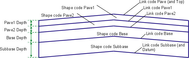
Pavement Structure on Paved Sections
The standard link codes from top to bottom are Pave, Pave1, Pave2, Base, and Subbase. The code Top is also assigned to all finish surface links, thus coinciding with the Pave links on paved sections. The code Datum is also assigned to the bottom of subbase. The shape codes for the material areas from top to bottom are Pave1, Pave2, Base, and Subbase.
The subassemblies that create paved sections have the depth or thickness of each layer as user-definable input parameters. Each subassembly that creates paved sections closes the layer areas to form a closed shape, even if those layers actually continue into the adjacent component. Layers can be omitted by setting the corresponding depth to zero. This collapses that layer so that the shape also has a zero area.