A set of standard codes define the display and behavior of the shape components used in the Autodesk Civil 3D Corridor Modeling subassemblies.
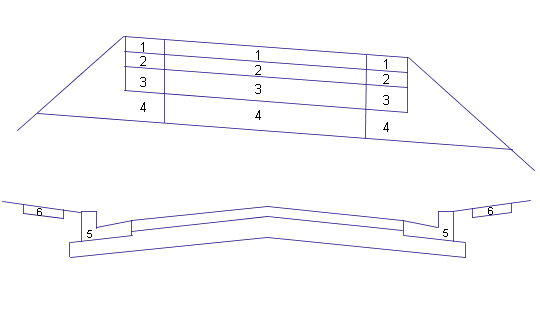
The following illustration shows the location of some standard shape codes on subassemblies defining an undivided road with a kerb-and-drainage channel:

Undivided Road with Kerb-and-Drainage Channel
The table below names and describes the standard shape codes used in the example assembly illustration.
|
No. |
Code |
Description |
|---|---|---|
|
1 |
Pave1 |
Closed shape between the finish surface and first pavement surface on paved sections. |
|
2 |
Pave2 |
Closed shape between the first and second pavement surface on paved sections. |
|
3 |
Base |
Closed shape between the second pavement surface and the base surface on paved sections. |
|
4 |
SubBase |
Closed shape between the base and subbase surfaces on paved sections. |
|
5 |
Kerb |
Closed area within a concrete kerb or kerb and drainage channel. |
|
6 |
Footpath |
Closed area within a concrete footpath. |
To view all actual code numbers, the code names and brief code descriptions: In Notepad, open C:\ProgramData\Autodesk\C3D <version>\enu\C3DStockSubassemblyScripts.codes.