A set of standard codes define the display and behavior of the point components used in the Autodesk Civil 3D Corridor Modeling subassemblies.
The following illustration shows the location of the standard point codes on subassemblies defining a divided road with a depressed central reserve and truncated shoulders.
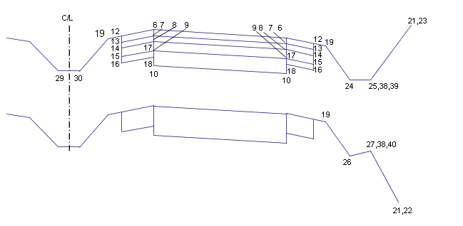
Divided Road with Depressed Central Reserve; Truncated Shoulders
The table following the illustrations provides descriptions of the point codes used in the illustrated assemblies.
The following illustration shows the location of the standard point codes on subassemblies defining a divided road with a depressed central reserve and extended shoulders:
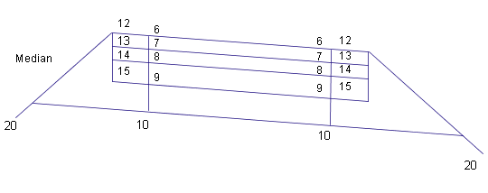
Divided Road with Depressed Central Reserve; Extended Shoulders
The following illustration shows the location of the standard point codes on subassemblies defining an undivided road with a kerb-and-drainage channel. Not all layers are shown.
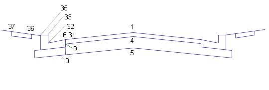
Undivided Road with Kerb-and-Drainage Channel; Not All Layers Shown
The table below names and describes the standard point codes used in the example assembly illustrations.
|
No. |
Code |
Description |
|---|---|---|
|
1 |
Crown |
Crown point between travel lanes on finish surface. |
|
4 |
Crown_Base |
Crown point between travel lanes on the base layer. |
|
5 |
Crown_Sub |
Crown point between travel lanes on the subbase layer. |
|
6 |
EC |
Edge of carriageway; inside or outside edges of travel lanes on finish surface. |
|
7 |
EC_Pave1 |
Edge of carriageway on the Pave1 layer. |
|
8 |
EC_Pave2 |
Edge of carriageway on the Pave2 layer. |
|
9 |
EC_Base |
Edge of carriageway on the base layer. |
|
10 |
EC_Sub |
Edge of carriageway on the subbase layer. |
| 12 | Lane_Pave1 |
Lane break point on Pave1. |
| 13 | Lane_Pave2 |
Lane break point on Pave2. |
| 14 | Lane_Base |
Lane break point on Base. |
| 15 | Lane_Sub |
Lane break point on Subbase. |
|
16 |
EPS |
Edge of paved shoulder; outer edge of paved portions of shoulder on finish surface. |
|
17 |
EPS_Pave1 |
Edge of paved shoulder on the Pave1 layer. |
|
18 |
EPS_Pave2 |
Edge of paved shoulder on the Pave2 layer. |
|
19 |
EPS_Base |
Edge of paved shoulder on the Base layer. |
|
20 |
EPS_Sub |
Edge of paved shoulder; outer edge of paved portions of shoulder on the Subbase layer. |
|
21 |
EPS_Base_In |
Inside edge of paved shoulder on the base layer. |
|
22 |
EPS_Sub_In |
Inside edge of paved shoulder on the subbase layer. |
|
23 |
ES_Unpaved |
Edge of gravel shoulder; outer edge of unpaved portions of shoulder on finish surface. |
|
24 |
Daylight_Sub |
Subgradient intercept point; point where the subbase surface extends and intersects the finish surface. |
|
25 |
Daylight |
Daylight point for a cut or fill slope. |
|
26 |
Daylight_Fill |
Daylight point for a fill slope. |
|
27 |
Daylight_Cut |
Daylight point for a cut slope. |
|
29 |
Ditch_Out |
Outside edge of ditch. |
|
30 |
Bench_In |
Inside edge of bench. |
|
31 |
Bench_Out |
Outside edge of bench. |
|
32 |
Flowline_Ditch |
Flowline of a V-shaped ditch. |
|
33 |
LMedDitch |
Left edge of central reserve ditch. |
|
38 |
Bottom_Kerb |
Bottom of kerb for a kerb without drainage channel. |
|
39 |
Back_Kerb |
Back of kerb. |
|
40 |
Footpath_In |
Inside edge of footpath. |
To view all actual code numbers, the code names and brief code descriptions: In Notepad, open C:\ProgramData\Autodesk\C3D <version>\enu\C3DStockSubassemblyScripts.codes.