Use this dialog box to set and edit the mapping of targets in subassemblies to the names of actual objects in the drawing.
The corridor Target Mapping dialog box is modeless so you can keep it open while you do other work. You can pin the dialog box open so it stays expanded or you can unpin the dialog box so that only the title is displayed when you move your cursor off the dialog box.

- Corridor Name
-
Displays the name of the selected corridor for which you are setting targets.
- Start Chainage
-
Displays the start station for the baseline in which the selected subassembly exists.Note: The Start Station and End Station values update depending on which subassembly is selected.
- End Chainage
-
Displays the end station for the baseline in which the selected subassembly exists.

- Expands the list of targets.

- Collapses the list of targets.

- Clears all filters from the list.
Note: You can filter the list by clicking on the column headings and entering a search term.

- Refreshes the list with any changes that have been made to the corridors in the drawing.
Offset and Elevation tab
Use this tab to specify offset and elevation targets.
- Subassembly
-
Displays the name of the subassemblies that require the targets. Expand the subassembly collections to display the targets to specify for those subassemblies. You can click
to expand the list of targets for the subassemblies.
- Baseline
-
Displays the baseline of the corridor.Note: The baselines that are displayed here are baselines where the assembly is in use and can have targets to other objects.
- Region
-
Displays the region of the corridor in which the subassembly is in use.
- Assembly
-
Displays the assembly in use for the corridor.
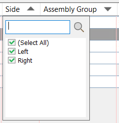
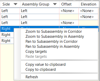
- Side
-
Displays the side of the assembly that the subassembly is attached to.
- Assembly Group
-
Displays the name of the assembly group.
- Offset
-
Specifies the offset or width targets. Click in a cell in this column to display the Set Offset Targets controls at the bottom of the dialog box.
- Level
-
Specifies the elevation or slope targets. Click in a cell in this column to display the Set Elevation Targets controls at the bottom of the dialog box.
Set Offset Targets/Set Elevation Targets
Use this section of the dialog box to specify the offset/width and elevation/slope targets. The title of this section changes depending on where you have clicked in the dialog box. If you click in a cell in the Offset column, the title is Set Offset Targets. If you click in a cell in the Elevation column, the title is Set Elevation Targets.
- Offset Range Filter
- Specifies a range by which to filter the available targets. Select the tick box and then enter a value to specify the offset. Only those targets that meet the filter requirements are then shown in the Select Entities to Target area.
- Select Alignment and Pipe to Target/Select Profile and Pipe to Target
- Specifies the alignments or pipes to target for offsets/widths or the profiles or pipes to target for elevations/slopes. The title of this section and the type of entity to specify changes depending on whether you select a cell in the Offset column or the Elevation column. Click
 to select an object in the drawing. Click
  to select the object by layer.
 - Select Feature Lines, Polylines/3D Polylines and Survey Figures to Target
- Specifies the feature lines, polylines or survey figures to target for offsets/widths or the feature lines, 3D polylines or survey figures to target for elevations/slopes by selecting them by layer. Select a layer name and then click
 to refine the selection of objects on that layer if needed. Click to select an object in the drawing.
 - Dynamic Layer Selection
- If a whole layer is selected as the target, new objects can subsequently be added to that layer and will be dynamically added as targets. All objects on the layer must be selected in order for the layer to be dynamic.
To update the corridor after objects on the layer have changed or have been added, one of the following workflows must be used:
- You must either have the corridor Target Mapping dialog box open when the layer has been changed or you must reopen the dialog box after the layer has changed.
- Alternatively, you can run the ForceUpdateCorridor command or the ForceUpdateAllCorridors command to force a rebuild of the corridor to apply the changes.
- The corridor does not get an out-of-date badge displayed on it in the Prospector tree when the layer has changed. If other aspects of the corridor are out of date which trigger the display of the out-of-date badge on the corridor in the Prospector tree, the Rebuild command will also apply the changes from the dynamic layer.
Note: The Rebuild command does not always work as expected even if a corridor is out of date and the out-of-date badge appears. The Rebuild command works only when the corridor becomes out of date because of the changes in the same region or the same baseline.
Important: Dynamic layer behaviour is not supported for layers in xrefs. If you add an object to a layer in an xref that has been selected as a target in the Target Mapping dialog box, the object will not be automatically selected as a target. To use the new object as a target, you must manually select the object by clicking next to the layer name in the Target Mapping dialog box to display the Select Entities dialog box and then selecting the object in the list.
- Selection Choice if Multiple
-
When specifying an offset target, you can use these settings to specify which offset to target if there are two or more targets in the Select Entities To Target list.
- Target to Nearest Offset
- Target to Furthest Offset
- Target to Flattest Offset
- Target to Steepest Offset
Surface tab
Use this tab to specify surface targets.
- Select a Surface for All Surface Targets
- Specifies a surface to assign to all surface targets. If the surface target is the same for all subassemblies, you can use this option instead of assigning each surface target individually.
- Subassembly
-
Displays the name of the subassembly that requires the target.
- Baseline
-
Displays the baseline of the corridor.
- Region
-
Displays the region of the corridor.
- Assembly
-
Displays the assembly in use for the corridor.
- Side
-
Displays the side of the assembly that the subassembly is attached to.
- Assembly Group
-
Displays the name of the assembly group.
- Target
- Displays the surface target. Click in a cell to select it and then use the drop-down list to select the surface to target.
- Rebuild Corridor
- Specifies that the corridor will be rebuilt. Select the tick box and click Apply or OK to rebuild the corridor.
Context Menu
Target Mapping Dialog Box (Earlier Version)
- Corridor Name
-
Displays the name of the corridor.
- Assembly Name
-
Displays the name of the assembly. If you are viewing the target for an entire corridor, for which there is more than one baseline, ‘**Varies**’ is displayed.
- Start Chainage
-
Displays the start chainage for the assembly’s region or the start chainage on the corridor baseline. If you are viewing the target for the entire corridor for which there is more than one baseline, ‘**Varies**’ is displayed.
- End Chainage
-
Displays the end chainage for the assembly’s region or the end chainage on the corridor baseline. If you are viewing the target for the entire corridor for which there is more than one baseline, ‘**Varies**’ is displayed.
The properties table contains the following columns:
- Target
-
Lists targets that are required by the corridor’s subassemblies, categorized into three groups: Surfaces, Width Or Offset Targets, and Slope Or Level Targets.
- Object Name
-
Opens either the Pick A Surface, Set Width Or Offset Target, Set Slope Or Elevation Target or Select Pipe Network dialog box, where you can select the Autodesk Civil 3D object name to map to the subassembly target.
Note: To quickly set all surface targets to the same surface object, click <Click Here To Set All> next to the Surfaces collection and select the surface object. - Subassembly
-
Displays the name of the subassembly that requires the target.
- Assembly Group
-
Displays the name of the assembly group.